PV solar power photovoltaik
Table of Contents
General
Information sources and todo:
- Aktuelle Fakten zur Photovoltaik in Deutschland – Fraunhofer PV Bericht August 2024
- PV-Pflicht in Baden-Württemberg
- Photovoltaik-Elektrosmog
- Design Your Own Raw LiFePO4 Cell Battery Solar Power System
- New to Life PO4 – great new thread on various voltage settings
- diysolarforum.com
- YouTube: Will Prowse, Andreas Schmitz and off-grid-garage.com
- Praxiserfahrungen mit einer Mini-Solaranlage im Jahr 2013
- Solaranlage
- install solar hot water panels along dachfirst
- install solar electrical panels along dachfirst or on south walmdach
- delzer decade-long experience with his solar pv system
- Verband unabhaengiger Energieversorger VESE Vortraege
- Bürokratiewahn bei der Anmeldung meiner DIY Solaranlage
Andreas Schmitz erklärt auf YouTube wie eine Anlage dimensioniert wird muss, damit sie sich schnell ökologisch und monetär amortisiert, Auswahl der PV Technologie und vor Auswahl des Aufbauortes, ab Minute 4:20 und ab Minute 5:25. Er nutzt PVGis – Photovoltaic Geographical Information System. Hier eine Schritt für Schritt Anleitung, um den Ertrag einer PV-Anlage zu berechnen.
Selbstbauprojekte zum Basteln und Experimentieren:
- Build-It-Solar – Plans, tools and information to help you build renewable energy and conservation projects.
- Mitch HotBox
- Kleine Solaranlage selber bauen
- Kleine 400W Solaranlage selber bauen
- GitHub repo with Information about Deye Microinverters et al
Links
- DIY Off Grid Solar Charge Controllers
- DIY solar electric projects forum
- Battery
- Laderegler solar charger
- LiFePO4 charge curve explained: no reason to charge above 3.45 or 3.5V; 3.36V at rest can still be fully charged; float voltage should be 3.35V-3.375V; never discharge below 2.5V; stop discharge at 3.15;
Components
- Solar panel: mounting, connecting, cables, diodes
- Charge controller: eur 100
- Battery: 4 x 3.2 V 280 Ah
- Battery management system BMS: ca. eur 500
- Inverter: co has a good one for eur 400
Systems
We are working with several separate small PV systems:
- PVH 800Wp balkonkraftwerk on south-facing hip roof: Absaar AB800A 800W Balkonwechselrichter + 2 x 410Wp Tidesolar TD-410MC-108HC
- PVL 800Wp balkonkraftwerk on south-facing balcony roof + east-facing first: NEP BDM-800 Microinverter + 2 x 410Wp Tidesolar TD-410MC-108HC
- PVM 2400Wp – offgrid east-, south- and vertical-facing panels with a 4.8 kWh 24V battery and three separate chargers
- PVN 900Wp – grid-linked system at the north end of the house; 4x275W Replus 250 microinverters, each fed by 3x75W used Wuerth panels
- PVS 900Wp – 3-phase grid-linked system on the south border wood stack; 3x300W SG300W microinverters, each fed by 4x75W used Wuerth panels
PVH
PV Hip roof &Ndash; 800Wp Balkonkraftwerk on the south-facing hip roof (walmdach) at south end of the house:
- Absaar AB800A 800W Balkonwechselrichter
- 2 x 410Wp Tidesolar TD-410MC-108HC panels all in black measuring 1724 x 1134 x 30 mm each
Done:
- buy electricity meters
- determine optimal angle for best yearly yield – nope, just use southern hip roof (walmdach)
- determine 220V connection point — do not plug into dgn wall socket, because that will confuse and invalidate the metering
- plan pv panel mounting – just use standard tiled roof mounting rail and bracket equipment
- buy Photovoltaik Solarpaneel Halterung 2x Montage Set Ziegeldach Aufständerung PV + extension for one aditional panel eur 70 + 35 = 105: 2024-08-27_firend24_pv_halterung.pdf
- walmdach triangle size and dimensions: bottom edge length 26 tiles x 22 cm = 5.72 m; top corner height 13 tiles x 33 cm = 4.29 m
- place 7 roof hooks dachhaken
- mount 2 rails length schienenlaenge 3 x 1.23 = 3.69 m > panelbreite 2 x 1.73 = 3.46 m
- connect 220V AC NYY-J 3 x 1.5 mm cable to inverter
- pick up panels from dieter
- mount pv panels
- connect pv panel dc cables to inverter
- lay cable from hip roof to balcony roof
- go through balcony roof into stairwell hallway
- mount cable conduit
- install fuse and electricity meter
- lay 220V cable to electricity meter
- hook up and start producing electricity
- determine absaar device serial number
- install absaar-ems inverter monitoring app
Todo:
- resolve absaar-ems inverter monitoring app login problem
PVL
800Wp balkonkraftwerk on south-facing balcony roof + east-facing roof ridge:
- NEP BDM-800 Microinverter
- 2 x 410Wp Tidesolar TD-410MC-108HC panels all in black measuring 1724 x 1134 x 30 mm each: panel E on main roof facing east, below ridge, with a slight south component, and panel S on balcony roof facing south, with a slight west component
Done:
- determine panel locations and orientation: directly below existing PVM panels
- buy microinverter: 2024-09-24_terralumen_wechselrichter.jpg
- determine microinverter device serial number – cannot find it anywhere
- buy pv panel mounting material: 2024-10-02_yayago_pv_montage.pdf
- install 220V cable through balcony roof to balcony roof panel – canceled, run it across on top of roof under the tiles instead
- determine exact PV mounting solution: attach top edge to existing PVM panels
- pick up panels from dieter
- extend panel E DC cables to reach down to the balcony roof: 13A x 30V x 5m → 5.3 mm^2 → 6 mm^2, not only 4 mm^2
- build working platform between DGN balcony and OGM balcony roof ridge
- place dachhaken and mount rails on main roof for panel E
- build metal strut to connect the two separate railing fragments on main roof – we skipped that after all
- prepare metal ribs to screw together pv panel edges – i did, but they didn’t fit, and i ended up using just washers
- mount east-facing main roof pv panel
- build working platform at balcony roof edge and drainpipe
- run DC cables from panel E under roof tiles down to the balcony roof – think of wind, rainwater, abrasion
- place dachhaken and mounting rails on balcony roof
- hook up 220V cable branch to microinverter across balcony roof ridge under the tiles
- mount balcony roof pv panel S
- connect pv panel dc cables to inverter
- start producing electricity
Todo:
- install and set up microinverter monitoring app
- test whether we can use NEPviewerCR
PVM
PV Middle, an off-grid system feeding moniwonig, galvanically separated from the mains grid by an automatic two-way switch, H-Tronik Umschaltstation. Due to suboptimal and conflicting panel orientations, PVM never reaches its theoretical peak performance. PVM maxes out at about 875W under the best possible conditions.
PVM supplies most of the required electricity for the rather frugal two-person moniwonig household consuming 456 kWh/year (2022) and consists of the following components, including three separate strings of PV panels and chargers, battery, BMS amd inverter:
- South facing: 400Wp PV panels + Renogy Rover 20A charger
- East facing: 400Wp PV panels + EPEver Tracer 3210AN charger
- Vertical facing with much shading: 1600Wp PV panels + Renogy Rover 40A charger
- Battery 24V, 8 x 3.2V LiFePO4 cells: EVE LiFePO4 3.2V 280Ah (previously VariCore 3.2 V 200Ah 3C LiFePO4)
- BMS: JK BMS 2A 20S JK-B2A20S20P (previously Daly Smart BMS)
- Inverter: 2500W Ective TSI 25 (previously PUGU)
- Energy generated in kWh: 2022: 653; 2023: 538; 2024: 506

It could generate more electricity, but there is nowhere to store it once all loads have been covered and the battery is full.
Due to the different panel orientations, neither of the first two can ever reach their theoretical peak performance. PVN maxes out at about 450W and PVM at ca. 875W under the best possible conditions.
Logs
Here are the PVM battery voltage, three charger currents and resulting Wh generated for a couple of days in October 2023, from Oct 2-4 and 5-10:
The sudden dips in the battery voltage indicate when the hot-water heatpump (ca. 500W) and the milk foamer (800W) are turned on.
Update Idea
Now that PVH and PVN are producing satisfactory results using microinverters, it might be a good idea to rebuild PVM based on that technology as well.
The 400W east-facing and south-facing panels could be connected to one single Absaar AB800A microinverter, and just use the vertical-facing panels with the existing 24V off-grid system.
- East 400 Wp: 4 x 100 W in series, max 5.56 A, max 88.8 V, max 400 W
- South 400 Wp: 4 x 100 W in series, max 5.62 A, max 88.4 V, max 400 W
- Absaar MPPT voltage range 33-55 V, max input current 2 x 14A
So, if I reconfigure both the east and south facing PV panel strings into 2 groups in series of 2 panels each in parallel, they each produce max. 44V and 11A, perfectly in range for the microinverter.
Bought an NEP BDM-800 microinverter that ought to fit the bill:
- DC input max 2 x 600W, voltage range 22-55 V, max input current 2 x 17A
Nope, PVM is still running, maybe just needs a new BMS, e.g., active JK instead of passive Daly.
Use the NEP microinverter for a new PVL system instead.
BMS Replacement
In October 2024, the PVM 200Ah 24V LiFePO4 battery with the Daly BMS started failing frequently. The BMS would disconnect the battery when the sun was shining too strong, and later systematically every night after sundown. Presumably, this was caused by the cell voltages drifting too far apart.
In the beginning of December 2024, I replaced the Daly BMS with a JK BMS, and suddebly all was well again. The cells are still a little bit apart, but the active balancer compensates enough for them to work fine with no interruprion.
VariCore LiFePO4 Cell Replacement
In January 2025, I replaced the VariCore 200Ah LiFePO4 cells with EVE 280Ah grade A- ones and performed some detailed logging:
EVE LiFePO4 Cell Replacement
End of April 2025, cell 7 of the new EVE 280Ah battery died; when charging, it is immediately full; when discharging, immediately empty.
I bought a new grade A EVE 280Ah (not A-) for from nkon eur 88 (2025-05-13_nkon_battery_eve_280ah.pdf) and installed that on 2025-06-17. I was unable to fully chanrge and equalise it with the others, so it was initially less fully charged than its siblings. I hope the BMS balancing will equalise them by itself.
Inverter Replacement
In August 2025, the PUGU inverter died. Probably, one of the cooling fans burnt out; it was running for a minute or two every four or five minutes for several years. I replaced it by a used one-year-old Ective TSI 25 inverter. Added a log entry of running the WWWP on battery power only on the first night to the cell data log.
PVN
Short for PV North.
PVN consists of 4 Replus 250 microinverters, each of them fed by 3 Wuerth 75 W panels.
Set up a grid-bound PV system on the north lean-to roof over the aussenkueche:
The microinverter handles max. 270W. 3 panels produce max. 225W, 4 max. 300W.
Initially I planned to connect 3 groups of 4 pv panels in parallel and a fuse to disconnect one of the four in case of overload. Some articles quote max. 220W for each microinverter, so I decided to use all four of them that I have anyway and just connect three panels in parallel to each one. So, 4 groups of 3 PV panels each in parallel, and we are well below the max inverter capacity.
PVN maxes out at about 450W under the best possible conditions.
done:
- calculate cable dimension using Kabelquerschnitt-Rechner: Netzform Wecheselstrom, Leistung 3 kW, Netzspannung 230V, Leitungsmaterial Cu, Leitungslänge 30m, Cos φ 0.9, maximaler Spannungsabfall 2.2%, Leitungsquerschnitt 2.4 mm2 → buy 2.5 mm2 cable, either feuchtraum or erdkabel
- bought 50m NYM-J3G2.5 feuchtraumleitung
- connect the pv panels with blocking diodes – nope, that reduces performance too much, and probably produces less gain than loss
- install new electricity cable from main fuse box to PVN + aussenkueche
- install two electricity meters and fuses for aussenkueche consumption and PV generated input
- built hooks to attach the inverters to the main roof beam
- installed the four inverters
- solder first group of 3 parallel pv panels and connect to first inverter
- solder and connect the remaining three groups of pv panels and inverters
- install a fuse and FI-schutzschalter for the new cable and hook it all up
shop:
- elektrokabel bauhaus – Feuchtraumleitung NYM-J3G2.5 50 m, Grau 48,88 eur – Erdkabel NYY-J3x2.5 50 m, Schwarz 55,57 eur
- 18 meter kabelkanal bauhaus 2 m x 30 mm x 15 mm 1,55 € pro Stück 0,78 €/m Regal 59 Feld 4 + 6
- Nigrin Kontaktspray?
PVS
Short for PV South. Set up a grid-bound PV system on top of the wood stack on the south border using 3 x 300W SG300MS microcontroller, each of them fed by 4 x Wuerth 75 W panels, each one feeding a different phase of the south 3-phase electricity.
- PVS1 phase 1 east
- PVS2 phase 2 middle
- PVS3 phase 3 west
Electricity generated in kWh by PVS1 + PVS2 + PVS3 (consumption reported by wld electricity meter):
2024-05-13 0.0 = 0.0 + 0.0 + 0.0 (372.2) 2024-05-17 1.6 = 0.0 + 0.0 + 1.6 (-) 2024-05-18 2.5 = 0.0 + 0.2 + 2.3 (374.6) 2024-05-19 4.8 = 0.4 + 1.1 + 3.3 (376.5) 2024-05-20 7.4 = 1.0 + 2.1 + 4.3 (379.2) 2024-05-21 8.5 = 1.24 + 2.56 + 4.74 (380.3) 2024-05-22 7.1 = 1.62 + 2.94 + 5.49 (382.2) (mitte reported kWh total 0.0) 2024-05-26 11.1 = 3.07 + 3.39 + 8.01 (388.9) (mitte reported kWh total 0.0)
done:
- built and covered wood stack
- built framework to hold panels
- connect a new 3-phase outlet to plug in the PVS system
- mount and connect 4 panels and PVS3 microinverer
- mount and connect 4 panels and PVS2 microinverer
- solder each of the three groups of 4 pv panels in parallel
- mount the remaining 4 panels, connect in parallel, connect PVS1 microinverter to the 3-phase plug
todo:
- test behaviour of the wld electricity meter; does it run backwards, or ignore the PV power, or measure it equally in both directions?
shop:
- drehstromsteckdose oder ch-herdstecker; nope, ended up using a german herdanschklussdose instead
- 3 x feuchtraumsteckdose aufputz
System Sizing
According to the MPP Solar system sizing guide, the most important and common questions every system designer faces are:
- How big of a solar array should I install?
- How big of a battery bank should I install?
These questions can be answered by using simple arithmetic operations. Solar array sizing requires calculating the total energy in kWh and divide it by the number of peak sun hours. Battery bank sizing also starts out with the total energy requirement, the backup days in case of no sun and the maximum battery DOD (depth of discharge):
Solar array sizing calculation:
Where
- W = peak wattage of the array required in kW
- E = daily energy requirement in kWh
- G = average daily number of peak sun hours on site
- Ksys = total system efficiency factor; varies, but may use 0.7 as average
Battery bank sizing calculation:
- Q = minimum battery capacity required in Ah
- E = daily energy requirement in Wh
- A = number of days of backup required
- V = system DC voltage in V
- T = maximum allowable battery DOD (Depth of Discharge)
- Kinv = inverter efficiency; equals 1 if there is no inverter
- Kcable = the efficiency of the cables delivering the power from battery to loads (typically 95-97% based on 3-5% loss)
Here is another PV sizing calculator by EPever that sums up loads, both daily and peak, and sizes batteries, solar panels, charger and inverter.
Auch beruecksichtigen: beim Heizen mit Solar und Wärmepumpe lohnt sich ein grosser Pufferspeicher besser als Akku.
Consumption
Treppenlicht
Beispiel Treppenlicht im Huenerbergweg 30:
- Verbrauch ca. 350 kWh p.a., im Schnitt ca. 1 kWh p.d., wobei im Winter sicher viel mehr pro Tag anfaellt
- Faustregel 1:1:1 – 0.35 MWh p.a. → 0.35 kWp (p steht für Peak) Solarmodul-Anlage und 0.35 kWh Akku als Richtwert;
- Ein 12V 30 Ah Akku entspricht rechnerisch 0.36 kWh.
Verbraucher:
- Klingeltrafo 4-6-8 V 1 A uses less than 15 W
- Treppenhaus Licht oben und unten je 15 W
- Kellerlicht 5 · 15 W
- Total max simultaneous load 8 · 15 = 120 Watt
- Assuming the Treppenlicht was running non-stop for 6 hours: 30 W · 6 h = 180 Wh
- So, to run just lighting and doorbells, 0.2 kWh ought to suffice; a 12 V 40 Ah battery will provide 0.48 kWh
- LED CRI 95 is good (natural sunlight is CRI 100)
- 450 LED flexible strip light roll 12V CRI 95 LED 3000K Warm White, ca. 10 Lumen per LED
- Prepare a 220 V charger for the 12 V battery, in case it runs out
- Lay a new 220 V cable from the 12 V solar power inverter down to the basement wall plugs
Maybe we ought to run a new 220 V line down to the basement, and just hook up the plugs to new wires.
We could also grab the 220 V for the plugs from the drehstrom installation…
Or both, in parallel, in case the battery runs out…
Moniwonig
Main consumer is Moni’s fridge: it uses 0.522 kWh per day, 190 kWh per year.
2021-04-07 18:00 started monitoring fridge electricity consumption using Pearl SD-2209-675, originally revolt SD-2209-675.
- 0.5 kWh per day might be satisfied by ca. 400 peak Watts, i.e., 3 qm solar panels
- 4 Stueck Solarpanel 100 Watt 12 V
- Lowest yield in November is ca. 15% of highest yield in July
- Assuming a July daily yield of 400 W · 0.7 efficiency · 6 h = 1680 Wh, the November one might be just 250 Wh
Moniwonig 2022-07-22
Empirical Moniwonig yield results February - July 2022; unfortunately, January is missing; the PV system was down then. East panel charger yield E from 400 Wp is what the charger fed into the battery or directly into the inverter. The consumption C is the 220 V AC consumption after the inverter from all three PV panel configurations E + S + V with a total of 0.4 + 0.4 + 1.6 = 2.4 kWp, partly shaded, including all system anbd conversion losses. E, C and average E and C per day in kWh on various dates between February and Julky 2022:
| date | days | C | E | C/d | E/d |
| 2022-02-05 | n.a. | 155 | 42 | n.a | n.a. |
| 2022-02-10 | 5 | 164 | 45 | 1.5 | 0.48 |
| 2022-02-20 | 10 | 176 | 48 | 1.2 | 0.30 |
| 2022-03-02 | 10 | 193 | 52 | 1.5 | 0.47 |
| 2022-03-19 | 17 | 221 | 62 | 1.7 | 0.56 |
| 2022-07-22 | 125 | 571 | 169 | 2.8 | 0.85 |
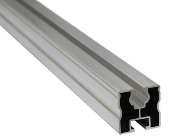
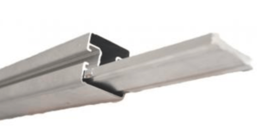
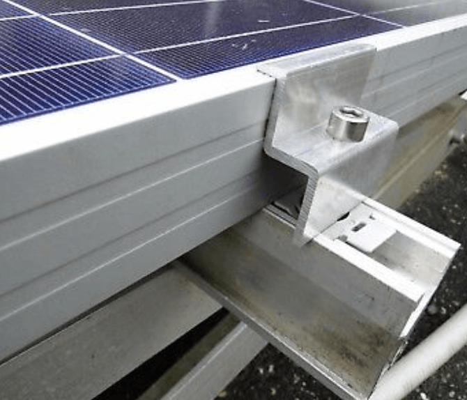
Mounting
Auf den Dachsparren unter den Ziegeln werden Dachhaken angebracht, die zwischen den Ziegeln hervorschauen und die PV-Montageschienen tragen. Die Schienen tragen die PV-Panele, die mit Klemmen befestigt werden. Schienen muessen eventuell zum Verlaengern miteinander verbunden werden.
Die Montageschienen muessen alle miteinander verbunden und geerdet werden; dazu muss ein Erdungskabel (16 mm2) an der Unterkonstruktion angeschlossen und mit einer sicheren Erdung verbunden werden.
- Montage und dabei zu beachten
- Erdung notwendig: Install a Dehn ground rod. Retrofit the house grounding system. Otherwise, PV forbidden.
- PV Halterung Module, Montagesystem for mounting the four panels on the balcony roof from Diether
- Second set of rails from bau-tech Solarenergie GmbH for mounting the four panels along the east-facing roof ridge
- Profiness GmbH, Broicher Waldweg 42, 45478 Mülheim a.d. Ruhr, Tel + 49-208/309619-0, info@profiness-shop.de
- For mounting 20 Wuerth panels on the north end of the east-facing roof, I bought 5 pieces of Stahlwinkeleisen verzinkt 20 x 20 x 3 mm, 6 metres long, for 150 euro + 50 euro fracht, from stahlshop.de
- PV verstellbar:
Solar Analysis
- Sonnenverlauf.de in Loe, or suncalc.org
- Solarkataster Baden-Wuertemberg BW: Solarpotenzial auf Dachflächen
- Solarkataster Lörrach – pretty useless
- PvGis photovoltaic geographical information system
- EU Photovoltaic Geographical Information System PVGIS, part of the European Commission EU Science Hub interactive tools
- PVGIS Monthly Irradiation Data
- Dachwinkel 45 Grad (horizontal tilt angle in Hamburg, Germany (53°N): the optimal tilt angle is close to 30°. At 45° tilt, the energy yield is stil very close to the maximum. This wide range of acceptable tilt angles makes roof installations attractive in higher latitudes
- Surface azimuth = angle from south to roof normal projected onto horizontal surface
- Dachausrichtung: Ostdach Azimuth -57 Grad (0 = Sued, -90 = Ost); Balkondach Azimuth +33 Grad
- 100 Watts requires ca. 0.7 qm solar panels
- 3D sun path by Andrew Marsh, explained in sky distribution
- mashup, but prefer Revit
- Ausrichtung und Neigung Tabelle
- Ausrichtung und Stromertrag
- Global-, Diffus- und Direktstrahlung mit Monats- und Jahressummen sowie Abweichungen vom Deutscher Wetterdienst
Sonnengang am Sonnenweg: unsere Nachbarin gegenueber Waldrain, teilt mit: Im Sonnenweg 3 scheint die Sonne von ca. 11 Uhr bis 11.30 Uhr (je nach Jahreszeit) durch und über den Waldrain, macht während des Tages ihren Gang, hat an Hochsommertagen von ca. 14 bis 14.30 Uhr an ihren Höhepunkt bis ca. 18 Uhr. Das heisst, sie gibt so viel Wärme, dass ich dann auf meine Terrasse Waldrain gehe und dort das hervorragende, ja herausragende, ja fantastische Waldrain-Feeling total geniesse… Gegen 18 Uhr gehe ich dann auf meine Sonnenrain-Terrasse und geniesse den Abend bis in die Puppen…
Frage: Was fuer ein Winkel und Ausrichtung ist fuer eine PV-Anlage optimal?
Antwort: Ca. 45° bringt den höchsten Jahresertrag. Wenn das Ganze in Richtung Autarkie optimiert werden soll, bringt eine Ost-West-Ausrichtung oder Süd-Ost / Süd-West einen gleichmässigeren Tagesertrag. Das kann aber auch eine Batterie ausgleichen. Für mehr Ertrag im Winter: steiler; dann wird dafuer im Sommer wird weniger Strom produziert und ins Netz gespeist.
Roof Surfaces
Analysis of potential pv panel placement roof surfaces in H30.
Dimensioning: on the north half of the house, each tile measures 20 x 33 cm. So, one square metre is 5 tiles wide and 3 high. On the south half, the tiles are slightly larger, ca. 225 x 336 mm, so 4 tiles wide x 3 high measure ca. 90 x 101 cm.
Also entspricht 1 quadratmeter exakt 5 x 3 Ziegel (b x h) auf der Nordhaelfte.
- E: east facing roof ridge – 57 degrees east + 33 degrees south, 45 degree angle from horizontal
- S: south facing balcony roof – 57 degrees south + 33 degrees west, ca. 40 degree angle S from horizontal
- V: vertical facing flat roof – 57 degrees north + 33 degrees east, ca. 10 degree angle N from horizontal
- W: south facing walmdach – 57 degrees south + 33 degrees west, 45 degree angle from horizontal, 27 x 13 tiles
The moniwonig PV system uses the first three E, S and V.
Remaining surfaces available:
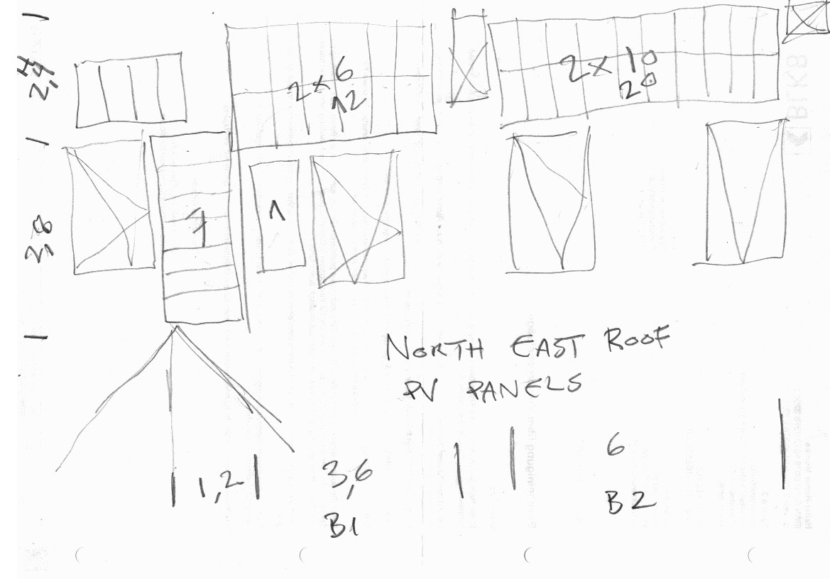
- NE top: east facing roof ridge rectangles above DGN windows: H 2.6, B1 3.7, B2 6.3, area 9.62 + 16.38 = 26 qm
- NE bottom: east facing roof ridge rectangles between DGN windows: H 2, B1 0.7, B2 2.8, B3 2.4, area 1.4 + 5.6 + 4.8 = 11.8 qm
- S: south facing balcony roof: 2.7 x 1.3 = 3.5 qm, max. 3 x 1.3 = 3.9 qm, max. max. 3.1 x 1.4 = 4.3 qm
- Walm: south facing walmdach rectangle below window: 4.2 x 1.5 = 6.3 qm
- SE bathroom dormer top: 1.5 x 1.6 facing vertically
- SE rectangle above bathroom dormer: 19 x 4 tiles (a 219 x 353 mm) = 4.1 x 1.4 = 5.9 qm
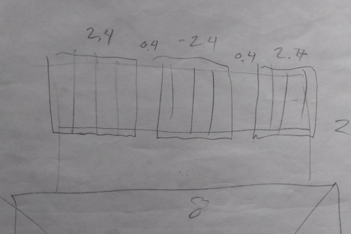
We have 40 Wuerth panels 0.6 x 1.2 each, 29.2 qm total. That would fit into E top + bottom. Top fits them in vertical pairs of 2 with a total height of 2.4, 6 + 10 wide = 3.6 + 6 meters. Or, equivalently, in vertical strings of 4 with a total height of 2.4, 3 + 5. That provides space for 32 panels out of 40.
In E bottom, we can place them in two groups of four each horizontally between the three windows, 1.2 meters high and 2.4 wide, taking care of the 8 but leaving no space for movement. Or, we add three higher up and further right, upright beside each other below the north chimney. Or, just two below the north window, tilted up from the roof and facing due south.
Better: add seven to the left of the roof division line, and one just right of it, cf. the NE roof pv panel arrangement sketch.
With the 40 panels on the NE roof, we have 3 kWp, Dachausrichtung -56 degrees (0 = S, -90 = E), Neigungswinkel 45 degrees. According to echtsolar.de PV-Ertragsrechner, the yearly yield will be 2712 kWh with only 73 and 76 kWh per month in december and janaury, respectively, over 2.3 kWh per day.
Comparing with the EGM + EGN consumption: in 2021, it was 1480 kWh for the entire year, ca. 4 kWh per day.
Scaling up the moniwonig yield from the existing E panels’ 400 Wp to the new panels’ 3 kWp, we may be able to achieve a factor 3/0.4 = 7.5 higher value; the minimum of 0.3 kWh/d converts to 2.25 kWh/d, pretty precisely matching the theoretical 2.3 kWh/d calculated above.
2022-08-24 update: I can only use 20 Wuerth panels. They can be placed on the east facing roof at the north end just below the roof ridge between the two north chimneys: w x h = 624 x 230 cm.
2022-08-25 new idea: cover the upper balcony with a solar panel roof to protect from both rain and sun. between the two chimney on the north-east quarter of the roof, that would provide an area of 30 qm. the axitec panels produce 200 Wp per qm, so 6 kWp on 30 qm. 12 axitec panels would require 12 x 1.75 = 21 qm. the wuerth panels produce only 100 Wp/qm; 20 x 0.75 = 15 qm.
Other panel placement options
- Above the sauna roof
- Above the south end of the shed roof, south of the maple tree, leaning back to almost touch both maple and walnut trunks
- On top of the wood pile at Herbert
- On a new shed on the Waldrain
Neigungswinkel fuer PV im Winter
Die Sonne steht im Sommer ganz anders, als im Winter. Im Winter ist der Eintreffwinkel der Sonnenstrahlen sehr flach. Die Sonne steigt im Winter nicht so hoch, wie im Sommer.
Die optimale Ausbeute einer Photovoltaikanlage wird dann erzielt, wenn die Sonne genau auftrifft (im rechten Winkel). Der optimale Neigungswinkel im Winter ist also viel höher, als im Sommer.
Dieser lässt sich sogar berechnen. Die Formel lautet (Dreilaendereck liegt auf ca. 47.6):
- optimaler Winkel
= 90 - (90 - Breitengrad - 23)
= 90 - (90 - 47.6 - 23)
= 70.6 Grad
Allerdings muss beachtet werden, dass die optimale Dachneigung im Sommer viel niedriger ausfällt. Insgesamt gibt es immer eine Mischkalkulation zwischen Neigungswinkel und Ausrichtung über den gesamten Jahresverlauf.
Several PV Panel Strings Facing Different Directions
Eine PV Anlage mit mehreren Ausrichtungen aber nur ein Wechselrichter – geht das?
- Es darf keine gröbere Verschattung vorliegen
- Es müssen für beide Strings Module mit denselben Eigenschaften verwendet werden
- Jeder Strang muss vollständig auf einer Dachseite liegen. Es dürfen keinesfalls Module unterschiedlicher Ausrichtung in Serie verschaltet werden
- Jeder Strang muss die gleiche Anzahl an Module haben
Solar Panel
Current sets of PV panels and directions:
- East 400 Wp – E – roof ridge facing east: 4 x 100 W in series → max 5.56 A, max 88.8 V, max 400 W, 149 W/qm, 49 c/W
- South 400 Wp – S – balcony roof facing south: 4 x 100 W in series → max 5.62 A, max 88.4 V, max 400 W, 183 W/qm, 48 c/W
- Vertical 1600 Wp – V – flat shed roof facing up: 7 x 2 x 115 W, seven serial pairs in parallel → max 32.9 A, max 65.6 V, max 1600 W, 111 W/qm
- Wuerth 3 kWp – 40 x 75 W, e.g., 4 strings of ten each → max 431 V, max 9.6 A at 340 V, max 3200 W, 102 W/qm, 26 c/W
- Trina 375 Wp –
South
This is the data sheet for the first four solar panels on the south-facing balcony roof for 192 euro, 48 cent/W.
Panel data:
- Solarpanel 100 Watt Polykristallin
- Nennleistung Pmax 100 Watt → 149 W/qm
- Spannung bei Nennleistung Vpmax 17,8 Volt
- Leerlauf Spannung Voc 22,1 Volt
- Kurzschluss Strom Isc 5,92 Ampere
- Strom bei Nennleistung Ipmax 5,62 Ampere
- Temperaturbereich -40°C / + 85°C
- Toleranz + /-5 %
- Solarzellen Polykristallin
- By-Pass Diode 12 Ampere
- Abmessungen 1000 x 669 x 30 mm (4 x 669 = 2676) → 0.67 qm → 149 W/qm
- Gewicht 8,1 kg
- Sicherheitsglas 3,2 mm
Array configuration: all four in series → max 5.62 A, max 88.4 V, max 400 W
East
Second set of four panels in series along the east-facing roof ridge for 196 euro, 49 c/W:
Panel data:
- Herstellernummer: YS100P-36_1er
- Max. Leistung: 100 W → 183 W/qm
- Max. Versorgungsspannung: 18 V
- Max. Leistungsstrom: 5.56 A
- Leerlaufspannung: 22.2 V
- Kurzschlussstrom: 5.89 A
- Abmessungen: 101 x 54 x 3 cm → 0.55 qm
- Gewicht: 6.3 kg
- Zellwirkungsgrad: 17.5 %
- Solartechnik: Polykristallin
- Marke: Yangtze Solar
Array configuration: all 4 in series → max 5.56 A, max 88.8 V, max 400 W
Vertical
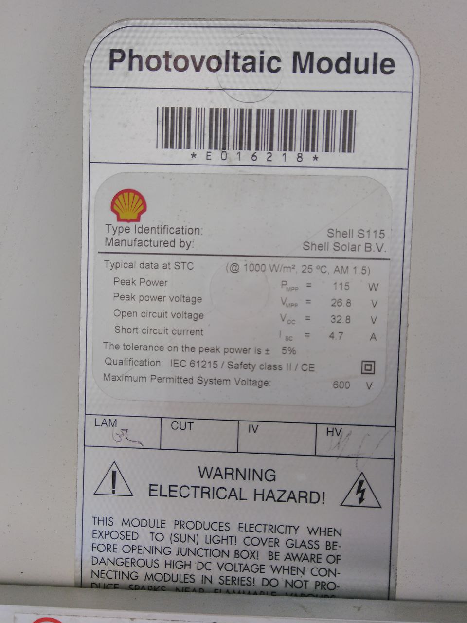
Horizontal shed roof with seven pairs of cbl used panels Shell S115 facing vertically and slightly north with some shade. Later: tilted them slightly southwards with a brick each.
Panel specs:
- peak power 115 Wp
- peak power voltage 26.8 V
- open circuit voltage 32.8 V
- short circuit current 4.7 A
- 850 x 1218 mm → 1.03 qm → 111 W/qm
Array configuration: 7 pairs of 2 panels in series each → max 32.9 A, max 65.6 V, max 1600 W; due to the shading, they will never reach that peak performance.
Cbl paid 500 for 20 panels with 115 W each, i.e., 22 c/W.
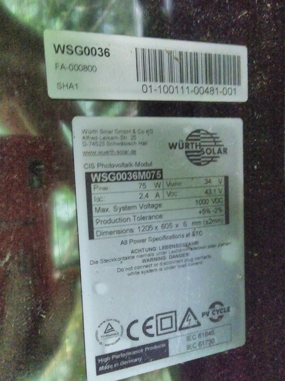
Wuerth
40 Stück 75W Würth Dünnschicht PV Solarmodule WSG0036M075 for 798 euro, 26 cent/W:
- 1205 x 605 x 6 mm → 0.73 qm, total 29.16 qm
- Pmax 75 W → 102 W/qm
- Isc 2.4 A
- Vmp 34 V
- Voc 43.1 V
- Max system voltage 1000 V
- Wpeak total 3 kW
Array configuration: a string of ten each would provide max 431 Voc and 340 Vmp with max Isc 2.4A, four such strings in parallel would provide max Isc 9.6 A. With 20 panels, two such strings of ten in series each would produce 340-430 V and 3.4-4.8 A.
The free space on the south facing balcony roof with 3 x 1.3 could accomodate 5 of these panels producing 375Wp.
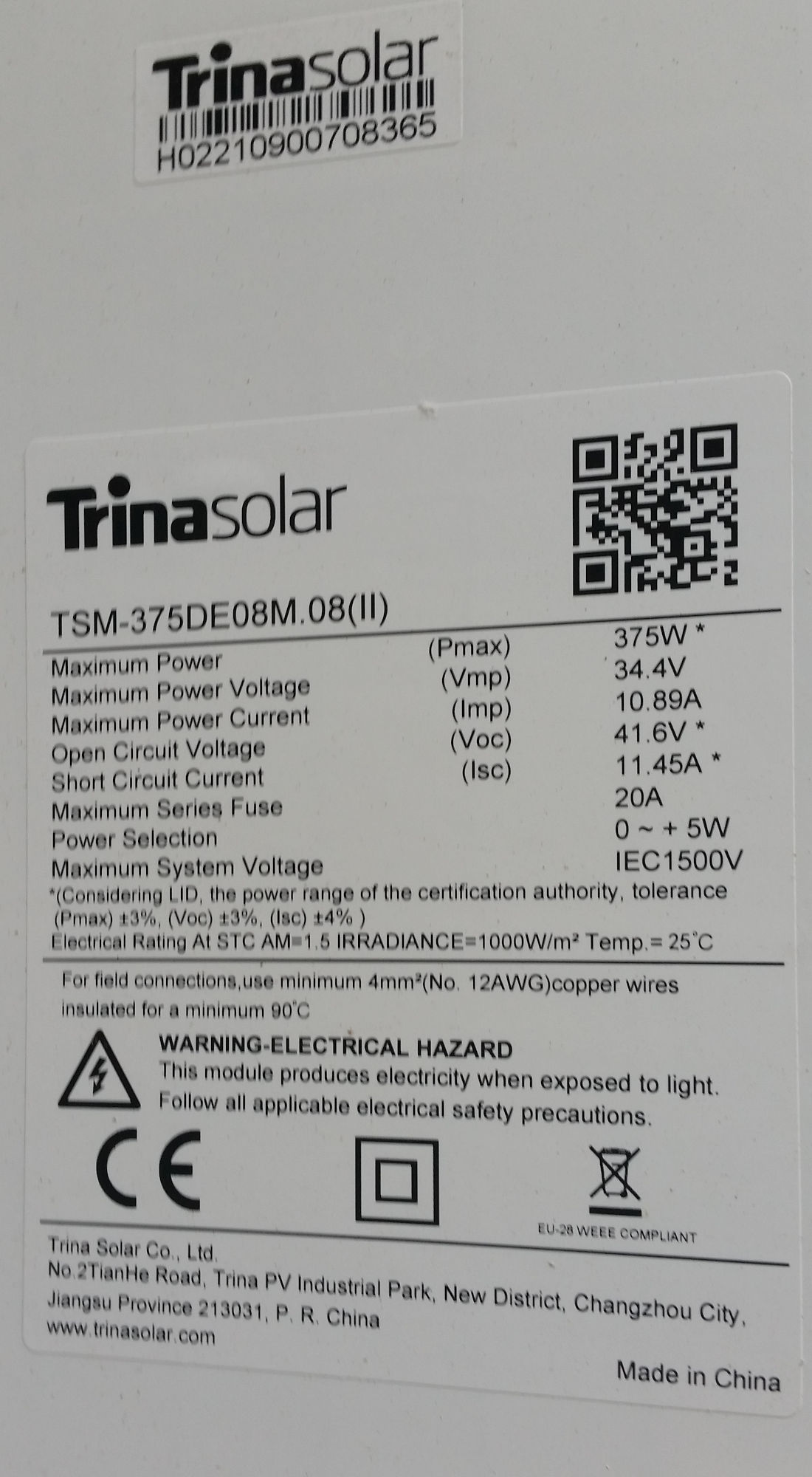
Trina
Trina PV panel with a broken glass cover, gifted by Marco.
- Dimensions 1043 x 1763 mm → 1.84 qm
- Max power 375 W → 204 W/qm
- Vmp 34.4 V
- Imp 10.89 A
- Voc 41.6 V
- Isc 11.45 A
Siemens SM 100-24
Wolfram offers 20 Siemens SM 100-24 panels. They were installed in 2002, 20 years ago.
- Electrical Parameters
- Pmax: 100 W, 80 W after 25 years
- Pmin: 90 W
- Imp: 2.95 A
- Vmp: 34 V
- Isc: 3.25 A
- Voc: 42 V
- Thermal Parameters
- Nominal operating cell temperature2: 45 +- 2 °C
- Change of Isc with temperature, : +1.2mA/°C (+0.04%/°K)
- Change of Voc with temperature, : -0.0775 Volts/°C (-0.34%/°K)
- Qualification Test Parameters
- Temperature cycling range: -40 to +85 °C
- Humidity, freeze, damp heat condition: 85 % RH
- Maximum system voltage: 1000 V per ISPRA (EC), 600 V per UL 1703
- Wind loading or surface pressure: 2400 N/m² (50 PSF)
- Maximum distortion4: 1.2 degrees
- Hailstone impact withstand: 25 mm at 23 m/s
- Physical Parameters
- Number of series cells: 72
- Length: 1316 mm
- Width: 660 mm
- Depth (w/o box): 40 mm
- Weight: 11.5 kg
- Area: 0.87 qm → 115 W/qm nominal, 92 W/qm after 25 years
- Warranty
- Power 90% after 10 years, 80% after 25 years
Axitec
Von Dubicki auf ebay:
- Peak power 360 W
- Uoc 40.92 V
- Umpp 33.69 V
- Isc 11.22 A
- Impp 10.69 A
- 1720 x 1020 mm → 1.75 qm → 205 W/qm
- 500 V / 41 V = 12 panels for the pip8048
- 140 euro / 360 W = 0.39 euro/Wp
- totals for 12 panels: 4320 Wp, 21 qm, 1680 euro
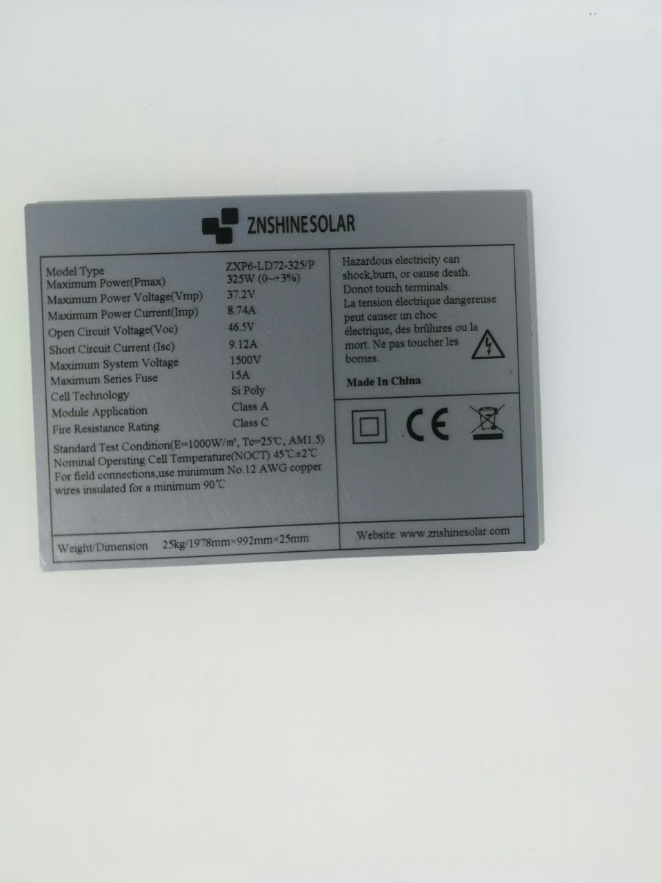
Znshinesolar
Joerg bzw. Detlev hat panele von Znshinesolar:
- Pmax 325 W
- Ump 37.2 V
- Uoc 46.5 V
- Imp 8.74 A
- Isc 9.12 A
- 25 kg 1978 x 992 x 25 mm → 1.96 qm → 165 W/qm
10 * 46.5 = 465 V 2 * 9.12 = 18.24 A 20 * 325 = 6500
Trimax
210-132 – TMX 655 MH9-132A
- 665 Wp
- Vmp 38.28 V
- Voc 46,24 V
- Imp 17,37
- Isc 18,78 A
- 2384 x 1303 x 35 mm → 3.11 qm → 214 W/qm
A string of ten would deliver 380 V, 17 A, 6460 W, on 31 qm.
The PIP8048MAX charger could handle two such strings, requiring 62 qm panel surface.
Let’s go for one array to start with: trimax 210-132 TMX 665 MH9-132A.
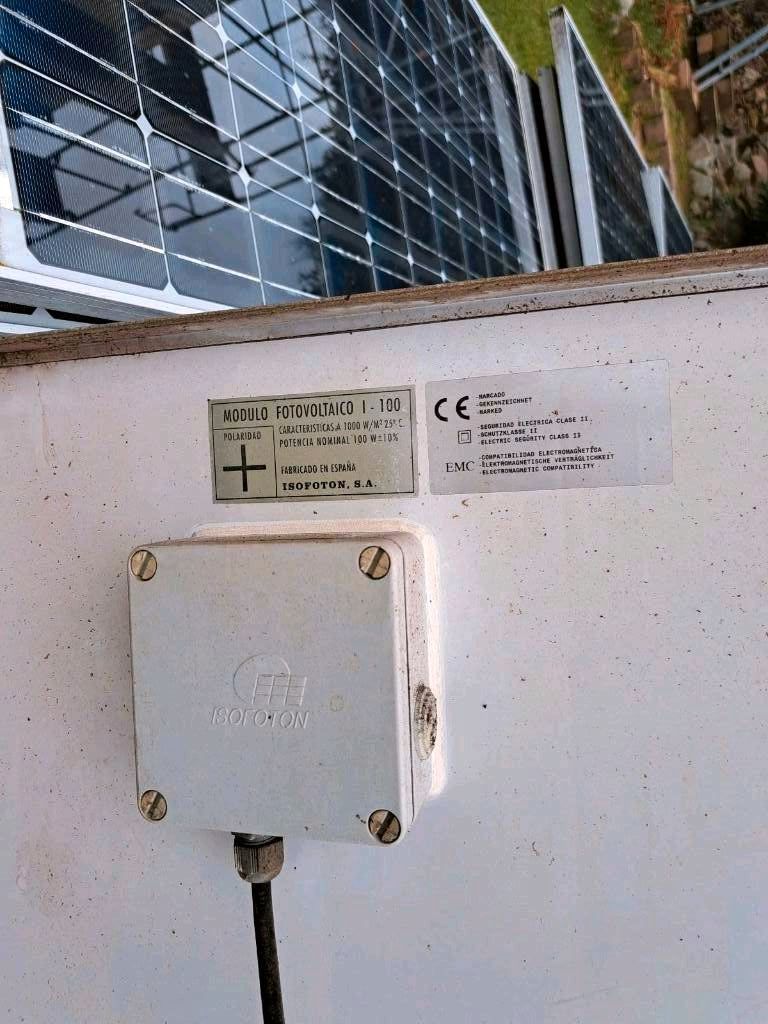
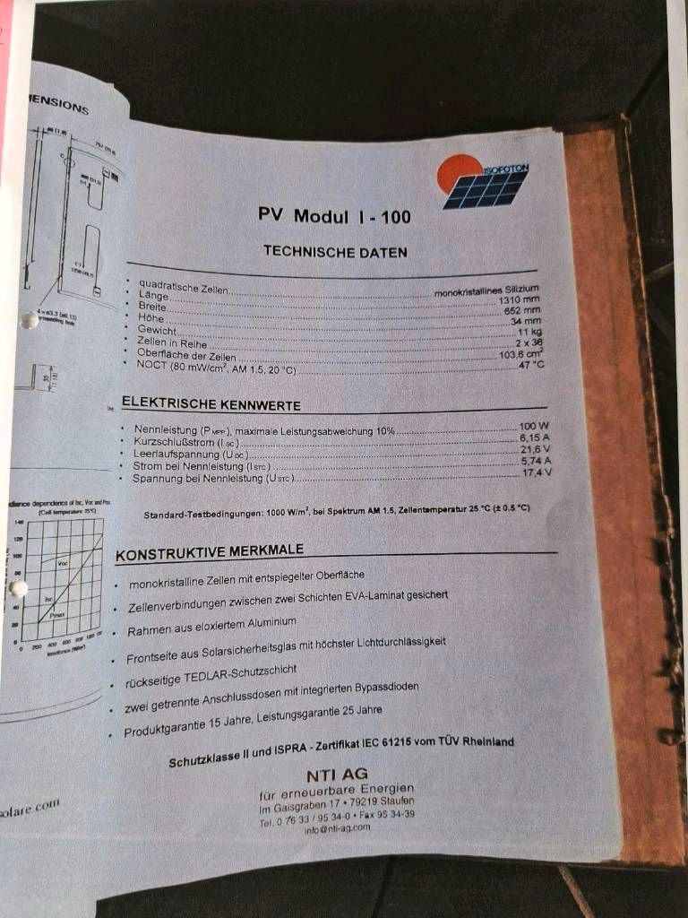
Isofoton
69 Isofoton modulo fotovoltaico I-100 monocristalline PV panels, used, 15-18 years old, leistungsgarantie 25 years, label, data, for 699 euro; assuming they still provide 80% of their nominal power, they will provide 5.5kWp and cost 13 cent/Wp:
- 100 Wp
- Vmp 17.4 V
- Voc 21.6 V
- Imp 5.74 A
- Isc 6.15 A
- 1310 x 652 x 34 mm → 0.85 qm → 117 W/qm
Tidesolar
Bought together with cbl and dieter four pallettes a 36 panels, 54 for dieter and 90 for me:
- TD-410MC-108HC all in black
- 1724 x 1134 x 30 mm
- 108 cell monocrystalline module
- 410W
- 20.97% maximum efficiency, -0% +3% positive power tolerance
- 15 year product warranty
- 30 year linear power warranty
We explore how to place Tidesolar PV panels on the H30 NE roof quarter:
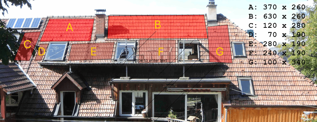
TD-400MC-108HC:
- 1724 mm x 1134 mm x 30 mm
- 400 W
- 37.1 Voc
- 30.87 Vmp
- 13.73 Isc
- 12.96 Imp
- 1500 Vmax
Areas A + B max size = 3700 x 2600 + 6300 x 2600 mm. Area A would fit 2 x 2 panels taking 3448 x 2268 mm. Area B would fit 3 x 2 panels taking 5172 x 2268 mm. That arrangement accomodates 10 panels providing 4 kWp.
meine berechnung in revit hat ja ca. 4.5 MWh/a ergeben. die sunny berechnung mit tide und 4 kWp auf eine etwas kleinere flaeche ergibt 3.8 MWh/a. das passt.
die problematischten monate sind ja januar und februar. in januar 2023 haben OGN + DGN zusammen 206 = 88 + 70 (3phasen) + 48 kWh verbraucht laut sunny produziert die tide-anlage in januar 117 kWh. bisschen knapp.
Let’s look at areas A + B + C + D + G. For the large panels, we had better combine C+D into one. C+D offers ca. 1900 x 1900, which can fit 2 panels taking 1724 x 2268, slighly overlapping the left-hand bottom corner of A. A still offers space for 4 = 2 x 2 panels as before, moved away towards the upper right. B hosts 6 = 3 x 2 panels. G can host 2 more. Finally, let’s switch from the 400W modules to 410W ones,
TD-410MC-108HC:
- 1724 mm x 1134 mm x 30 mm
- 410 W
- 37.5 Voc
- 31.2 Vmp
- 13.88 Asc
- 14.15 Amp
- 1500 Vmax
ET-M754BH410WW/WB Tier One:
- 1722 x 1134 x 30 mm
- 410 W
- 37.32 Voc
- 31.45 Vmp
- 13.95 Asc
- 13.04 Imp
- 21.0% efficiency
18 panele verlegt, 7380 Wp, flaeche ziemlich ausgereizt; jedes blaue rechteck ist 1730 mm x 1140 mm gross, 6 x 6 mm groesser als die pv-panele:

- Sunny Design proposal
- Bill of materials:
| Component | Amount | Note |
|---|---|---|
| Roof mounting hook | 52 pc | Dachhaken |
| Mounting bracket | 57 m | Montageschiene |
| Bracket connector | 8 pc | Schienenverbinder |
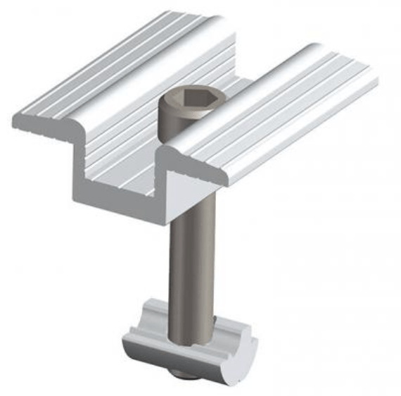
| End clamp | 30 pc | Endklemme |
| Middle clamp | 21 pc | Mittelklemme |
| PV panel | 18 pc | TD-410MC-108HC 7380 Wp 675 Voc 14.15 Imp |
| PV cable 2 metre | 4 pc | 700V 15A 5mm diameter 19mm2 cross section area |
| PV cable 9 metre | 2 pc | |
| PV disconnector | 1 pc | DC circuit breaker + surge protection + fuses |
| Inverter | 1 pc | 1000V DC in 230V 3 phase 8kW AC out |
| Storage | 1 pc | 20kWh 48V DC battery |
Detailed list of mounting bracket dimensions, total 56.6m, assuming panel size including clamps 1.2 x 1.8 m:
- 2 x 3.7m
- 2 x 4.8m
- 4 x 1.2m
- 4 x 2.4m
- 1 x 5.4m
- 3 x 6.6m
Dachhaken: 3 + 3 + 4 + 4 + 2 + 2 + 3 + 3 + 4 + 5 + 5 + 5 + 2 + 2 = 47 Stueck.
Cables
- ct-Artikel: Kabel fuer Photovoltaik auswaehlen und verbinden
- 12-minute video on soldering solar connectors
To select a suitable wire gauge and cable size, please refer to the cable wire size gauge chart and Aussendurchmesser gebraeuchlicher Kabelquerschnitte.
Typische Wechselstromkabelquerschnitte:
- Q = Querschnitt (mm²)
- Cu = Kupferleiter-Ø (mm)
- A = Ader-Ø mit Isolierung (mm)
- K = Kabel-Ø gesamt (NYM-J 3×)
| Q | Cu | A | K |
|---|---|---|---|
| 1,5 | ~1,38 | ~2,8–3,0 | ~8–9 |
| 2,5 | ~1,78 | ~3,2–3,3 | ~9,5–10,5 |
| 4 | ~2,26 | ~3,7–3,8 | ~11–12 |
| 6 | ~2,76 | ~4,3–4,5 | ~13–14 |
I bought wire from zaehlerschrank24.de.
My rooftop panels are connected with 6 mm2 solid copper wire:
- East: 400 Wp, 4 x 18 = 72 V, 5.56 A
- South: 400 Wp, 4 x 17.8 = 71.2 V, 5.62 A
Up to 10 meters length and 40 A current, a 6 mm2 wire is enough.
I bought 100 m of 6mm2 ‘xenes’ cable from lichtex and asked them the details; they reply: Hartgezogenes Kupfer, verzinnt. Mehrdrähtiger Leiter, Klasse 5 IEC60228; bei 20 °C betraegt der Winderstand R pro Meter fuer 4mm² ca. 5.1 × 10⁻³ Ohm, fuer 6mm² ca. 3.2 × 10⁻³ Ohm.
On the flat roof, placed seven pairs of cbl used panels:
- 230 Wp, 2 x 30 = 60 V, 4.7 A
Since 7 x 4.7 = 32.9 < 40 A, the 6mm2 wire should suffice for all seven pairs.
Measuring Charger and Inverter DC Currents
The battery, chargers and inverter will generate the following maximum currents:
- B and I: max 2500 W → max ca. 100 A
- E: EPEver Tracer 3210AN max 400 W from PV → max 16.7 A
- S: Renogy Rover 20A max 400 W from PV → max 16.7 A
- V: Renogy Rover 40A max 1040 W from charger → max 43.4 A
Cables from the charge controllers to the battery and inverter: resistance calculator says R = ca. 0.001 ohn. With a 10 A current, that should generate a voltage differential of ca. 0.01 V or 10 mV.
Using a INA121 instrumentation amplifier with a gain of 100 to monitor that would map the interval [0,20A] to [0,1V]. It supports gains between 1 and 10000.
Using Arduino Uno to measure voltage, we have six ADC input pins (A0-A5); a multiplexer feeds one of the six into the ADC. The standard setup measures voltages between 0V and 5V with a resolution of 4.9mV.
Todo: measure the precise resistance of the five individual pieces of cable.
Blocking and By-Pass Diodes
- solar-facts: Blocking and by-pass diodes in solar panels
- couleenergy: Blocking and bypass diodes in solar panels and solar PV systems
- diysolarforum: Bridge rectifier as a blocking diode
- windandsolar: How to install a blocking diode
- Do your circuits need a Schottky diode?
cbl used panels include three diodes each, type IR50SQ100 or 50SQ100, Vishay Semiconductors Schottky Diodes & Rectifiers 100V 5A Schottky DO-204AR. Are two of them blocking and one the bypass? If not, then we may need to add blocking diodes before hooking up all our pairs in parallel.
Nope, testing revealed that they are all three by-pass diodes, for the three strings of cells integrated in each panel. Applying a voltage across the poles of an unlighted panel sends current through it ‘backwards’. So, I added my own blocking diodes.
I bought 50 pieces Master Instrument (MIC) SR5100 Schottky diodes (datasheet). Unfortunately, they have a forward voltage drop of 0.85 V, so we loose 4.7 A x 0.85 V = 4 W of peak power from each pair of panels. Ah, I see now how the type is encoded: SR5100 stands for SR-5-100, a Schottky rectifier with a rating of 5 A and 100 V.
Semitransparent
Frage zu 50% halbtransparente lichtdurchlaessige PV-elemente, die Strom erzeugen und auch Licht durchlassen: Die koennte man ja eventuell aufs Dach machen, und auch als Fenster benutzen, oder?
Antwort: Als Dach oder Fenster wäre der Dämmwert zu schlecht, aber z.B. als Dach eines Wintergartens o.ä. Vielleicht auch fuer Dachausbau, z.b. einen unbeheizten hellen Bewegungs- und stillen Raum oben unter dem Sueddach.
Charge Controller
- E: EPEver Tracer 3210AN max 400 W from PV → max 16.7 A
- S: Renogy Rover 20A max 400 W from PV → max 16.7 A
- V: Renogy Rover 40A max 1040 W from charger → max 43.4 A
Illuminating YouTube videos on charging:
- Battery charge voltages explained: equalization, bulk, absorption and float
- Float charging Lithium batteries
- No equalisation
- Set absorbtion equal to float, e.g., to 13.4 V for 80% SOC
- LiFePo4 and absorption: charge with constant current until a certain voltage is reached, e.g., 3.55 V, then switch to constant voltage and continue until the current drops down, e.g., to a small percentage of the maximum battery amperage.
- Cell balancing
SOC
Monitoring the state of charge:
- Victron Smartshunt (local)
- VictronSmartShunt-ESPHOME – ESPHome component to monitor a Victron BMV and SmartShunt via ve.direct / UART TTL
- Victron community discussion on API for Bluetooth 500 Smart Shunt access
Otto
Otto got his charger from offgridtec; Kundenberatung + 49-8721/7786187 (Mo - Do 08 - 12 und 13 - 18 Uhr, Fr 08 - 14 Uhr). He uses a https://www.amazon.de/FCONEGY-Balance-Ladeger%C3%A4t-LCD-Balance-Ladeger%C3%A4t-Adapter/dp/B07TMYCV8R to charge all kinds of different battery types.
EPEver Tracer 3210AN
I am currently using the EPEver Tracer 3210AN, an acronym, meaning:
- 3 → charge and discharge current 30A
- 2 → 24V system
- 10 → 100V max PV open circuit voltage
- AN → common negative system
Documentation:
Some measured data on solar irradiation on balcony roof:
- 2021-06-25 13.1 V before a full day of sunshine.
- 2021-06-26 13.7 V after a full day of sunshine the day before. At 12:10 full sunshine, but still 0.0 A. At 16:50 still 13.7 V and 0 A. Apparently, the charges stops charging the battery at 13.7 V.
So, I need to modify the charger control settings!
- How to use the EPEver PC software for charge controllers
- Configure epever tracer settings: CC-USB zu RS-485 Konverter, SolarV GmbH, tel + 4961969076877, info@solarv.de, tel China + 86-10-82894112, info@epever.com
Here are my initial EPever Tracer 3210AN solar charger settings for the east and south facing panels on August 30 2021.
Settings recommended in the discussion on struggling with basic LiFePO4 settings in Epever Tracer, adapted for 24 V:
- Over Voltage Disconnect 29.4 V
- Charging Limit Voltage 29.2 V
- Over Voltage Reconnect 29.2 V
- Equalize Charging Voltage shut off or 28.8 V
- Boost Charging Voltage 29.2 V
- Float Charging Voltage 27.2 V
- Boost Reconnect 26.6 V
- Low Voltage Reconnect 20 V
- Under Voltage Warning Reconnect Voltage 23 V
- Under Voltage Warning 23 V
- Low Voltage Disconnect 22 V
- Discharging Limit Voltage 21 V
- Equalize Duration 0 or set as low as possible
- Boost Duration 180 minutes
Lower values are recommended to reduce battery stress, e.g., in Epever controller 90% 20% soc charge parameter Q. Interesting note from there (adapted for 24 V):
In practice, if the resting voltage is below 25 V, it’s getting low; above a resting of 26.8 V, it’s nearly full.
2021-09-03: changed my boost duration from 120 to 180. Maybe I should lower it to 10 or even 0 instead?
Tracer RS485 Communication
Links for communicating with and controlling the EPEver Tracer:
- Python code and RS485 protocol RJ45 connector cable pins for communicatiing with EPEver Tracer 3210AN
- Tracer RS485 Modbus-Blynk, an Arduino project to connect the EPEver Tracer MPPT Solar Controller RS-485 Modbus to an ESP8266 and monitor it using the Blynk mobile app
- Epever RS485 to wifi adaptor
- Wingoneer USB 2.0 to RS485 serial converter adapter CP2104 SN75176
- Silabs CP2104 drivers, CP210x VCP Mac OSX Driver
- Arduino Reading Solar Charger COM via MODBUS (MAX485)
- Capture and Analyze Solar Power Generation Metrics with Python and InfluxDB
Tracer RS485 Cable
RS485 standard:
- 5V – orange + white
- 5V – orange
- RS485 B – green + white
- RS485 B – blue
- RS485 A – blue + white
- RS485 A – green
- GND – brown + white
- GND – brown
I used the following pins, standard colour coding, my 4-wire cable with red wires and 1, 2 and 4 black stripes, resp.:
- pin 3 – RS485 B – green + white – red with 1 black stripe
- pin 5 – RS485 A – blue + white – red with 2 black stripes
- pin 7 – ground GND – brown + white – red with 4 black stripes
Atached to a chopped off half of a cable marked:
- UTP CAT 5E PATCH ISO/TEC 11801 & EN 50288 & TIA EIA 5E8B.2 3P 24 AWG X4P Type CM (UL) C (UL) CHH E1785589
I guess UTP = unshielded twisted pair; X4P = times four pairs…
With that cable and the MacOS driver for the USB-RS485 adapter, jtracer can successfully query parameter data from the EPEver Tracer 3210AN.
Tracer Charging Limit
2025-09-16: I want to limit the Charging Limit Voltage down to 28V. I tried to create a script to achieve that in the jtracer repo. I gave up in the end and used the EPEver Windows software instead, cf. LLM chat logs in the repo readme and the current EPEver charging settings.
Renogy Rover
Renogy Rover 40A
On 2022-02-04, I installed a Rover Li 40 Amp MPPT Solar Charge Controller for the horizontal panels:
- Nominal System Voltage: 12/24V Auto-Detect
- Rated Charge Current: 40A
- Max. PV Input Voltage: 100V
- Max. PV Input Power: 12V/520W, 24V/1040W
- Power Consumption: <100mA/12V; <58mA/24V
- Temperature Compensation: -3mV/°C/2V
- Max Battery Voltage: 32V
- Electrical Protection: Overcharging, over-discharging, overload, short circuit. Capable of charging over-discharged lithium batteries.
Renogy Rover 20A
On 2022-03-10, I installed a Rover Li 20 Amp MPPT Solar Charge Controller for the south-facing panels:
- Nominal System Voltage: 12/24V Auto-Detect
- Rated Charge Current: 20A
- Max. PV Input Voltage: 100V
- Max. PV Input Power: 12V/260W, 24V/520W
- Power Consumption: <100mA/12V; <58mA/24V
- Temperature Compensation: -3mV/°C/2V
- Max Battery Voltage: 32V
- Electrical Protection: Overcharging, over-discharging, overload, short circuit. Capable of charging over-discharged lithium batteries.
Warranty registration:
- Purchase Date: 10.03.2022
- Product Category: controller
- SKU with Country Code: RNG-CTRL-RVR20-DE
- Serial Number: 205231800178
- Ebay Order Number: 373691158278
Renogy Rover RS232
2025-09-16: I am trying to modify the battery charging settings to retain the battery SOC within a window between 20% and 80% SOC. I looked at using a Python script, but cannot implement that immediately due to the lack of a suitable cable to talk with the Rover RS232 serial interface via its six-pin RJ12 port. I then tried to use the manual UI built in to the chargers, but they do not provide access to the parameters without purchasing a custom Bluetooth dongle, e.g., the BT-1 Bluetooth Module. So, back to the custom cable… The renogymodbus Python package documents the cable setup but provides only read-only functionality. The renogy-rover-modbus repo includes two scripts, one to report the status ande the second to set appropriate register values. How to build the cable and what components to use, e.g., a USB RS232 TTL serial UART adapte with FTDI chip FT232RL and RJ12 plug.
Arduino Charger
Battery
Must read how to find happiness with LiFePO4 batteries; LiFePO4 charge settings cheat sheet, translated from 12 to 24 V:
- Bulk/Absorb: 28.4 - 29.2 Volt
- Absorb time: 0 - 2 hours
- Float: 27.2 Volt or less
- No temperature compensation
- No equalize, or 29.2 Volt
Chart of voltage vs capacity for a 3.2V LiFePO4 cell and a 24V LiFePO4 battery combined from the article (above) and the graph (below), latter marked with an apostrophe ‘:
| V | % | |
| 3.650 | 29.2 | 100'-100 (charging) |
| 3.450 | 27.6 | 99.5' |
| 3.400 | 27.2 | 100 (resting) |
| 3.375 | 27.0 | 99' |
| 3.363 | 26.9 | 96' |
| 3.350 | 26.8 | 90'-99 |
| 3.325 | 26.6 | 80'-90 |
| 3.313 | 26.5 | 65'-70 |
| 3.300 | 26.4 | 60'-70 |
| 3.288 | 26.3 | 55-55' |
| 3.275 | 26.2 | 40-50' |
| 3.263 | 26.1 | 40' |
| 3.250 | 26.0 | 30-30' |
| 3.225 | 25.8 | 20-25' |
| 3.200 | 25.6 | 17-20' |
| 3.150 | 25.2 | 14' |
| 3.125 | 25.0 | 14 |
| 3.000 | 24.0 | 9-9.5' |
| 2.800 | 22.4 | 5' |
| 2.500 | 20.0 | 0-0' |


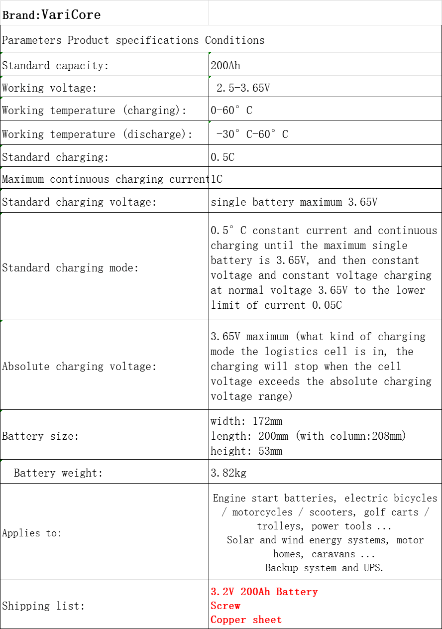
LiFePO4 8S VariCore 3.2V 200Ah
24 V system: 25.6 V battery, max charge 29.2V, min discharge 20V – 8 cells VariCore 3.2 V 200Ah 3C LiFePO4, 3.82 kg, 200 x 172 x 53 mm, working voltage 2.5-3.65 V for euro 560 – specification – akkudoktor thread on 24V DIY Batterie: neue Zellen parallel zu den alten schalten?
These cells were not good. However, I used them for the PVM system round the clock from summer 2021 until december 2024, 3.5 years. In that time, PVM generated 116 + 653 + 538 + 506 = 1813 kWh, which would cost less than eur 730 from the grid. Seeing that the battery cells + BMS alone cost about 600 euro, disregarding panels, chargers, installation etc., the ROI is definitively negative.
In March 2025, Beni (Klaus Nachbar) tested 7 of the 8 cells (one was dented and not tested) by executing one cycle of full charge CHG, full discharge DCH, full charge and discharge to 40% SOC for storage:
| Nr | V | m0hm | CHG Ah | DCH Ah | |
| 2 | 3.294 | 0.25 | 172.12 | 172.14 | |
| 3 | 3.297 | 0.27 | 163.74 | 164.82 | |
| 4 | 3.297 | 0.26 | 173.46 | 173.44 | |
| 5 | 3.300 | 0.27 | 170.35 | 170.59 | Defektes Gewinde an Minuspol |
| 6 | 3.299 | 0.28 | 175.24 | 175.57 | |
| 7 | 3.298 | 0.29 | 171.28 | 171.97 | |
| 8 | 3.295 | 0.28 | 159.99 | 160.14 |
He also noted:
- The pole connector plates were much too thin for 100A, let alone 200A
- The cells need insulating from each other; the blue wrapping plastic is much too thin; if it is damaged on both cells and they short circuit, it can release a 20’000A burst
EVE LiFePO4 3.2V 280Ah
EVE LiFePO4 16S LF280K 3.2V 280Ah: Originally planned for a 48V system; 16 x LiFePO4 3.2V prismatic battery cells for $2227.20 incl. shipping from Docan Power, specification; standard charge and discharge is 0.5C, i.e., 140A for EVE 280Ah; 1C is 280A; the peak current is 2C, 560A.
Other Batteries
- cbl old 12V 100Ah 100A 1200W power GTK lithium lifepo4 battery BMS 4S 12,8 V: Betriebsspannung 10-14.6 V, Überladungsschutzspannung 14.6 V + 0.05 V, Entladungsschutzspannung 10V + 0.05 V
- cbl new: 4 x VariCore 3.2 V 280Ah + LiIon batterey management system
- Otto’s old battery: 12 V YellowTop 75 Ah (ca. 0.9 kWh) max charge 14.8 V, six cells, min 1.8 V x 6 = 10.8
- Q&A on solar panel short circuit
- DIY: 11kWh Batterie für die Solaranlage & das richtig günstig
- Andreas Schmitz’ 22kWh LiFePo4 Akku für 3000€ – Specifically, he strongly recommends ensuring that the battery cells cannot expand, swell, grow. Polfett. JK BMS. Working range 3-3.4 V = 48-54.4 V. Infrarotkamera to check for heating due to bad electrical connections.
Salt Battery
Falk has built a 30 kW peak PV system. He plans to expand to 100 kW and start storing energy in salt-based batteries.
Bidirektional
V2H is vehicle-to-home, V2G vehicle-to-grind; Vehicle-to-Grid kann die Lebensdauer von Batterien in Elektroautos verlängern.
BMS Battery Management System
I first tried a Daly Smart BMS. Initially, I could not get that to work. I then switched to ther i-tecc BMS, but that did not balance the cells, and switched off when they consequently got unbalanced. I tried to add the heltec active balancer in parallel with the i-tecc BMS, but that did not help. The second time around, I got the Daly Smart BMS to work after all. It performed more or less OK until October 2024, when it started to shut off the battery both when the sunshine was strong, charging too much, and at night, with no charge at all; apparently, it was not balancing the cells well enough. I replaced it by a JK-B2A20S20P BMS in December 2024, and all was well again.
LibreSolar Open Source BMS
- Libre Solar building blocks for DC energy systems: Battery Management Systems
Daly Smart BMS
- AliExpress SouthLan Store for 87 euro in June 2021: Smart BMS 8S LiFePo4 24V 100A.
- Manuals
- Downloads from dkenergy akku-lifepo4.de
In hindsight, Daly BMS is not recommended. It is cheap. However, it is a passive balancer. It balances the cells by burning excess energy. It was always somewhat unreliable, switching off the battery unnecessarily, often when there is too much sun, so the battery voltage hits some upper limit, or the cells drift apart when fully charged. In October 2024, it started switching off the battery at night as well, with no sun at all. I decided to replace the Daly balancer for the original 24V battery. The JK BMS active balancers are recommended in many forum discussions.
i-tecc BMS
I then switched to a more expensive 200 euro non-smart German BMS LiFePO 8S 150A 24V by i-tecc:
- Nennspannung: 25.6V (24V)
- Ladespannung: 28.8V (8 · 3.6V)
- Überspannungsschutz: 3.9V ± 0.025V (8 · 3.9 = 31.2); Freigabe 3.8 V (30.4 V)
- Tiefentlade-/Unterspannungsschtz: Aktivierung 2.1V, Freigabe 2.3V
- Ladestrom max.: 150A
- Entladestrom: 150A
- Balance-Strom: 110mA ± 10mA
- Überlastschutz: 500A
- Eigenverbrauch: ≤20µA je Zelle
- Temperaturüberwachung: ja
- Detailed specification
That worked fine right out of the box. However, there is no way to monitor it or read any data from it. Futhermore, it does nothing at all to balance the cells until the battery voltage reaches 28.8 V. I was only able to find that out by calling and asking.
Maybe it does do some balancing after all, however; on 2021-10-30, the bms turned off due to cell imbalance and cell #2 going below its minimum; ever since, they seem to be doing quite well, even though cell #2 keeps lagging behind the others; 2021-12-16, after months of use and never reaching 28 V, they appear to be almost perfectly balanced.
JK BMS 2A 20S JK-B2A20S20P
I bought a JK-B2A20S20P from AliExpress IC GOGOGO Store recommended by Andreas Schmitz for 181 euro (2022-08-12):
- Specification and operation manual
- 8S-20S
- 2A balancing current
- 200A continuous discharge current
- 350A maximum discharge current
I originally planned to use the JK-B2A20S20P for my 48V battery, but never got around to building that. So, the BMS remained sitting unused in its pristine state until December 2024.
In December 2024, I replaced the Daly BMS on the original 8S 200Ah LifePO4 battery by JK BMS, and the battery immediately worked perfectly again with no problems whatsoever.
The JK BMS iOS app runs well on the MacBook PC:
According to the manual, the red LED is the Bluetooth connection indicator; it is always on when Bluetooth is connected to the BMS, and flashes when disconnected.
In January 2025, I removed the 200Ah Varicore battery cells, replaced them by the 280Ah EVE cells instead, and set up the JK-B2A20S20P to manage them. Funnily, the Macbook JK BMS apps is unable to log in and write to the BMS to modify the settings. I had to install the JK BMS app on an Android phone instead. The Macbook app is still fine for reading the values, though.
JK BMS 2A 8S JK-B2A8S20P
In October 2024, I decided to replace the Daly passive balancer for the original 24V battery.
I ordered an active BMS JK-B2A8S20P from the HankzorBMS Store on AliExpress for EUR 70; Hankzor is recommended in the diysolarforum:
- JK-B1A8S20P User Manual (local link)
- 4S-8S
- 2A balancing current
- 200A continuous discharge current
- 350A maximum discharge current
- Jikong web site
In January 2025, I passed this 8S JK BMS on to Rene, together with 8 of my 280Ah LiFePO4 cells.
Balancer
A discussion on using an active balancer with Daly BMS explains the cell quality and the concepts and uses of active versus passive balancing. If you stay in the middle (flat) part of the voltage curve and avoid discharging below the knee at ca. 15% SOC, the BMS passive balancer should be able to handle the cell balancing with no need for an additional active balancer.
Heltec Active Balancer
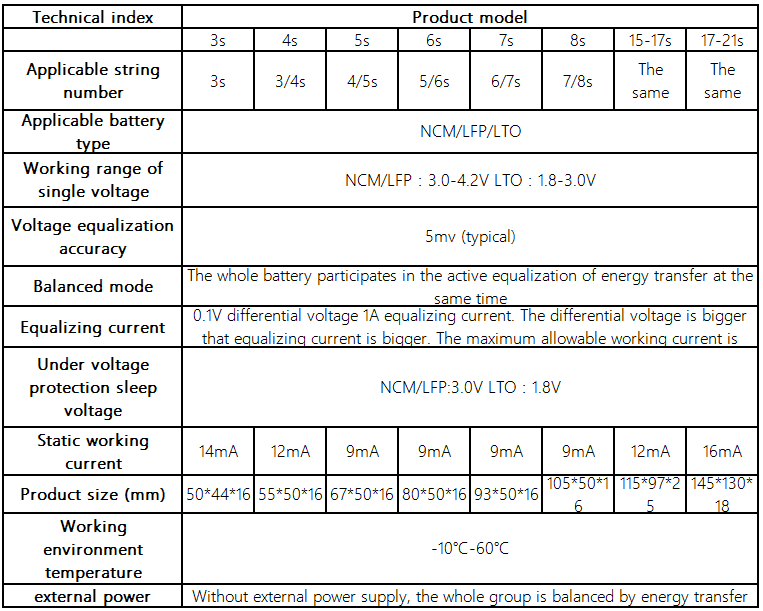
The i-tecc BMS does not start actively balancing until the battery reaches 28.8 V, i.e., 3.51 V per cell. Unfortunately, that has never happened yet. I therefore purchased an additional 55 euro active LTO/LiFePo4/NCM balancer by Heltec BMS providing 8S 5A capacitive active equalization from LTO-Store, Andreas Petermann, Neuffen, tel. + 49-1520/8767231:
Capacitive active energy transfer equalization board (high precision 5mv, whole set of equalization, not adjacent equalization) Working voltage 2.7V-4.5V, suitable for ternary lithium, lithium iron phosphate, lithium titanate. Working principle: the capacitor fit transfers the charge carrier, and the balancing work is started when the balancing board is connected to the battery. The original brand new ultra-low internal resistance MOS, 2OZ copper thick PCB, balancing current 0-5.5A, the more the balancing current, the smaller the battery. Reserve the wiring position of the dormant switch, the operating current in dormant power-off mode is less than 0.1mA, and the equilibrium voltage accuracy is within 5mv. The quiescent current is about 12 mA; it is recommended that the battery capacity should be suitable for batteries with 60-300Ah. With under-voltage sleep protection, voltage below 3.0V will automatically stop entering the sleep state; standby power consumption is less than 0.1 mA. Specifications
Inverter
Neutral Ground Bonding
Some inverters do not implement a neutral ground bonding, cf., how does your inverter deal with ground. In my case, I have 220V between the two inverter AC power output lines, but neither of them is neutral ground. Compared with ground, one has 90V and the other 130V. I have a RCCB (FI-Schalter) installed, and that is not triggered. So be aware! There are no ‘neutral’ and ‘phase’ lines; both AC power lines are ‘hot’.
The neutral and ground wires should be “bonded” together at the main panel only, cf., understanding neutral, ground, grounding, and bonding.
Inverter earthing and N-G Bonding in a simple off-grid setup discusses neutral ground bonding and also the difference between high-frequency and low-frequency inverters; mine is a high-frequency, and a low-frequency inverter would be better. For the concrete wiring, refer to the video on off-grid inverter consumer unit grounding:

Victron Phoenix
I temporarily hooked up an old used Victron Phoenix inverter: Manual for Phoenix Inverter Compact 1200 and 1600.
Bad news: Data communication with Victron Energy products says that the victron inverter communicates using VE.Bus and nothing else. “VE.Bus is our proprietary protocol used by the Inverters to synchronize their AC outputs. There are VE.Bus communication ports on our Inverters, Multi’s and Quattro’s. The synchronization feature is mission-critical. Direct third-party connections are not allowed. All interfacing has to be done via Modbus TCP (preferred), “VE.Bus to CANbus/NMEA2000 interface”, or via the MK2/MK3”. To obtain official Modbus TCP requires a victron color control gx device, which costs around eur 500 on ebay. so, i would say, forget it. i see no realistic way to hook up these inverters or communicate with them at all.
Good news: Connecting your Victron product to a computer with VE Configure says that VE configure II is a program used to configure settings/options on a Multi or Quattro, connecting your Victron product to a computer and that Phoenix Chargers, Phoenix Multi (including Compact) and larger Phoenix Inverters are all compatible with VE configure. All other models are not. So, maybe it is possible to configure and control the Phoenix after all.
Easun Power
Easun Power Official Store pure sine wave inverter DC 24V AC 220V 2500W inverter with LED display
- Continuous Rated Power: 2500W
- Peak Power: 5000W
- Low voltage protection: 20V
- High voltage protection: 30V
- Conversion rate: 93%
- Eight intelligent protections: overload, high voltage, low voltage, over temperature, reverse polarity, short circuit, over current, insurance
- Up to 93% conversion rate, 30% conversion loss, 30% continuous power
- Temperature control fan: temperature ≤ 45 °C, the fan stops; temperature ≥ 45 °C, the fan starts
- Buzzer: when any protection of the inverter is triggered, the inverter will immediately disconnect the power supply, the load enters protection mode and the buzzer sounds
I wrecked this one by attaching PV panels directly to the inverter. That worked fine as long as the battery was happy. At oner point, though, the BMS turned it off, the voltage rose too high, and the inverter was destroyed.
PUGU
PUGU 2500W/5000W reiner sinus Spannungswandler Wechselrichter 24V 230V Inverter mit USB for eur 186 mit 5 Jahre Garantie.
- Dauerausgangsleistung 2500W
- Max. kurzfristige Spitzenleistung 5000W
- Eingangsgleichspannung 24V DC
- Ausgangswechselspannung 230V AC
- Regelbereich ±5%
- Frequenz 50Hz±3%
- Wirkungsgrad >87%
- Leerlaufstrom 0.8A
- Ausgangswellenform reine Sinuswelle
- Klirrfaktor 2%
- Temperatuschutz (75±5)℃
- Schutz vor geringer Eingangsspannung JA
- Verpolungsschutz JA
- Schaltungsschutz JA
- Schutz vor Kurzschluss JA
- Schutz vor Überlast JA
- Nettogewicht 3.5±0.05 kg
- Grösse 380 x 180 x 90mm
2025-08-15: the PUGU inverter broke, presumably the cooling fan failed. I replaced it on 2025-08-19 by a more reliable Ective TSI 25 inverter.
MPP Solar PIP8048MAX Charger-Inverter
8 kW PIP8048MAX from MPP Solar, tel 010017-00886.2.8797.8896. ordered per email to sales@mppsolar.com.
- Max continuous output 8 kW
- Support for two PV panel array inputs; each input supports:
- Max PV input voltage 500 V, 8 kW, MPP voltage 90-450 V, 18 A (450 x 18 = 8.1 kW)
- Max charging current @ 48 VDC 120 A (utility + charging) (5.7 kW)
- Max AC power 8 kW, max current 60 A (13 kW)
Ective TSI 25
ECTIVE TSI 25 Sinus-Wechselrichter 2500 W / 24 V mit Netzvorrangschaltung NVS, USV und ECTIVE RC 2 Fernbedienung; bought it used on ebay for 280 euro, original purchase date of first owner was April 2024; new for 359 euro directly from ective (incl. 19% MwSt VAT that can be refunded).
- Manual
- FI-Schutz
- E-Mail info@ective.de
- Servicetelefon +49-7141/1410870 Mo-Fr 8:00-12:00
Hybrid Inverter
Balkonkraftwerk anmelden oder nicht, vgl. ComputerBild – Meldepflicht von Stecker-Solaranlagen – Balkonkraftwerk ohne Anmeldung betreiben: Welche Folgen das haben kann.
Nicht Anmelden gilt als Ordnungswidrigkeit und kann laut Energiewirtschaftsgesetz eine Geldbusse nach sich ziehen. Bislang ist ein solcher Fall aber nicht bekannt.
GMI Grid Tie MPPT Microinverter
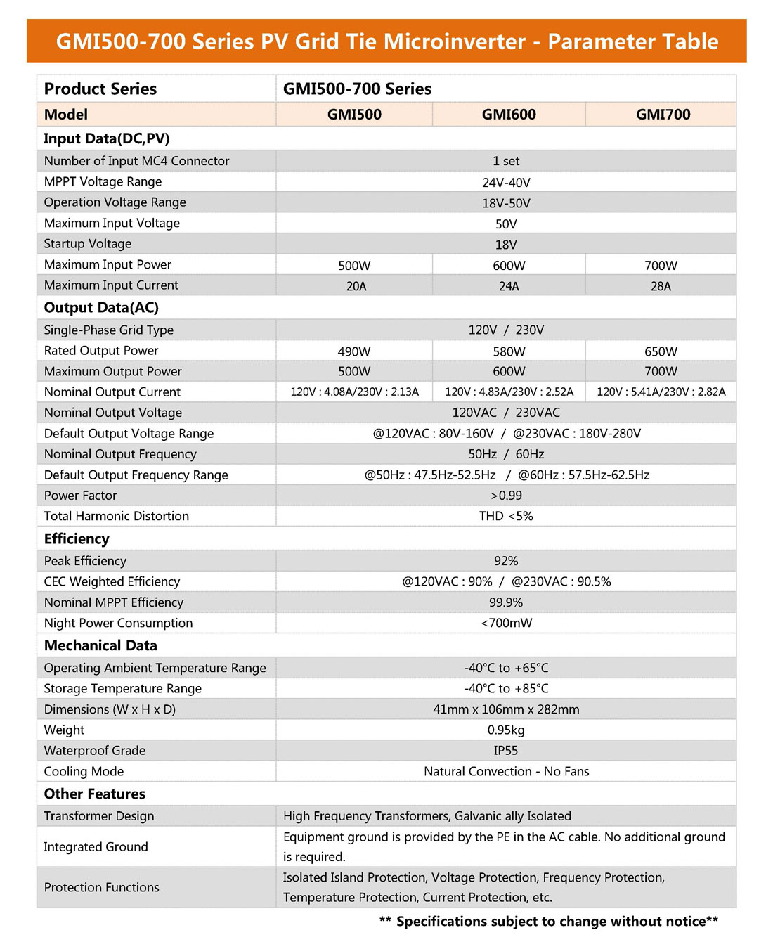
I bought a GMI 600W DC 18-50V grid tie MPPT micro inverter for 86 Euro:
- Specs
- MPPT Voltage Range: 24V - 40V
- Maximum Input Power: 600W
- Maximum Input Current: 24A
- Rated Output Power: 580W
- Maximum Output Power: 600W
- Peak Efficiency: 92%
- Nominal MPPT Efficiency: 99.9%
I hooked it up with the Trina panel (375 Wp) on a sunny and slightly hazy February afternoon and it produced between 80 and 120W AC power. Trina produces max 11A at 34Vmp, so I could add 5 of the Wuerth panels (34Vmp, 2.4A max, 12A from five of them) in parallel to the Trina panel. Or I could populate it with 10 Wuerth panels and use the Trina elsewhere, maybe on the south-facing balcony roof, with a new dedicated 24V charger. 10 Wuerth panels can be placed in a rectangle of 6 x 1.2 or 3 x 2.4 metres.
It stopped working after a few hours, and I was unable to diagnose any problem, so I returned it again.
Replus 250 Microinverter
In March 2023, I bought four Renesola Replus-250 micro inverters from ebay Kleinanzeigen, 4 x Wechselrichter für ein Balkonkraftwerk Replus 250, for 60 euro incl. delivery:
Operating Instructions: The Replus-250 is powered on when sufficient DC voltage from the module is applied. The status LED will start flashing as an indication that it is live:
- Standby: LED flashes on 2 seconds and off 2 seconds
- Producing power: LED flashes on 1 second and off 1 second
- Producing power and communicating with MRG: LED flashes on 0.5 seconds and off 0.5 seconds
- Max. PV-Generator Power 270 Wp
- Max. DC Voltage 55 V
- Maximum input short circuit current 14 A
- MPPT efficiency > 99.5%
- MPPT DC Voltage Range 22 ~ 45 V
- Max. Units per Branch Circuit 15
- Nominal AC Power 225 W
- Nominal AC Voltage 230 V
- Nominal AC Voltage Range 200 ~ 270 V
- AC Power Frequency / Range 45.5 ~ 54.5 Hz
- THD (at Nominal Output) < 4 %
- Power Factor > 0.95 cosφ
- Peak. Efficiency 96.3 %
- CEC Efficiency 95.0 %
- Power consumption at night < 0.17 W
- Dimensions (WxHxD) 230 x 138 x 35 mm
- Weight 2.0 kg
One Replus 250 could be attached to three (or four?) Wuerth panels in parallel. They would deliver max. 225 W (3 x 75), 7.2 A (3 x 2.4), 43 V, taking 1830 x 1205 mm space (3 x 605).
The south balcony roof provides 3000 x 1275 mm and could take four Wuerth panels easily, or even five at a pinch, feeding two Replus 250. The rectangle above bathroom dormer facing east has 4.1 x 1.4 m. We can place three Wuerth with one Replus on the balcony roof, 1.85 x 1.2, and 6 Wuerth + 2 Replus on the rectangle above the flat-roof dormer, 3.66 x 1.2.
AC connector plug: Wieland Steckverbinder RST25I3S B1 ZR2SV BG03, available on ebay for eur 10, dust- and waterproof according to IP67 IP code.
By the way, I happened to learn that an improvement over standard 1-phase microinverters might be possible with a three-phase grid-connected microinverter for AC photovoltaic module applications.
SG300W Microinverter
Similar to NETek SG300MS, SG = solar grid, 300W, M = medium operating voltage 18V-50V, MPPT voltage 24V-40V, S = single MC4 connector pair, cf. NETSGPClient).
On 2024-01-22, I bought three RundeGestz Micro Solar Inverter SG300W for eur 64 per piece: 300W Mikroinverter fuer Balkonkraftwerk Wifi WLAN MPPT to implement PVS and cover the wood stacks on the H30 south border with PV and balkonkraftwerk: 5.4 x 2.4 meter using 12 of the remaining wuerth panels, 4 panels a 75W each for each of the three inverters, connecting the three sets to the three phases of the south side drehstrom.
- Specifications and instructions
- DC Min 20V, MPPT 28V-55V, Max 60V 10A 300W
- AC 230V Max 1.3A; AC bus plug RC-H19 RoHS, one male, one female, 3Pol. RC-H19; M16? M19?
- Smart Life - Smart Living monitoring software: model SG300MS, inverter id PVS1 east 19001213, PVS2 middle 19001114, PVS3 west 10991189
Absaar AB800A Microinverter
- Adaptive photovoltaic power: 210-560 W x 2
- Starting voltage: 30 V
- Full MPPT voltage range: 33~55 V
- Working voltage range: 16~60 V
- Maximum input current: 14A × 2
- Maximum input short-circuit current: 25A x 2
- Number of MPP trackers: 2
- Rated output power: 800 W
- Rated output current: 3.48 A
- Rated mains voltage*: 230 V (single-phase)
- Mains voltage range: 180~264 V AC
- Rated mains frequency: 50 Hz/60 Hz
- Max. total harmonic distortion: <3% (nominal capacity)
- Power factor: >0.99
- Max parallelism: 5 pcs.
- Protection against island formation: Yes
- AC short circuit protection: Yes
- Max. efficiency: 96.70 %
- Protection class: CLASS I
- Protection level: 1P67
- Cooling method: passive cooling
- Monitoring: W-LAN
- Ambient temperature range: -40°C ~ +65°C
- Manufacturer’s warranty: 10 years
- Dimensions (LxWxH): 225 mm x 225 mm x 37 mm
- Weight: 3.25 kg
- Device serial number: WWA3511103
- VC: 25ZZ4
- AbsaarEMS App for Android – iOS
NEP BDM-800 Microinverter
DC Input
- Recommended PV Module Power Range 600W x 2
- MPPT Voltage Range 22-55V
- Startup Voltage 24V
- Max. Input Voltage 60V
- Max. Input Current 17A x 2
- Overvoltage Protection Category II
AC Output
- Peak Output Power 800VA
- Max. Continous Output Power 750VA
- Rated Output Voltage 230V
- Nominal Output Voltage Range Configurable
- Max. Continous Output Current 3.26A
- Nominal Frequency / Range /Hz 50 / Configurable
- Power Factor (Nominal/Adjustable Range) 1.0/0.9 leading … 0.9 lagging
- AC Short Circuit Fault Current Over 3 cycles 8.2 Arms
- THDi@Rated Power < 3%
- Max. Units per 20A Branch 5
- Overvoltage Protection Category III
Efficiency
- Peak Efficiency 97.30%
- MPPT Efficiency > 99.5%
- Night Power Consumption 110 mW
General Data
- Operating Ambient Temperature Range -40~65 degrees Celsius
- Relative Humidity Range 0-100%
- Dimensions (W x H x D) 268 x 250 x 42 mm
- Weight 2.9 kg
- DC Connector Type MC4
- AC Connection Type (inverter-inverter) Trunk Cable
- Communication Method PLC or WiFi
- Protection Class IP-67
Zaehlerschrank
Was ist eHZ zählerschrank? – elektronische Haushaltszähler
- Hoehe: Alle neu installierten Zählerschränke müssen einen zweireihigen, plombierbaren oberen Anschlussraum (300 mm) aufweisen, d.h. Standardzählerschränke besitzen eine Höhe von 1100 mm, Zählerschränke mit zweistöckigen Zählerplätzen eine Höhe von 1400 mm. Andere Höhen sind für Zählerschränke nicht mehr zulässig.
- Kosten: Das günstigste an solchen Arbeiten ist der Zählerschrank selbst – der kostet je nach Ausführung und Größe nämlich meist nur rund 20 EUR bis 100 EUR. Der wirklich teure Teil ist die Erneuerung des Innenlebens durch den Elektriker. Die Erneuerung des Sicherungskastens ist nicht günstig.
Komplett ausgestattet sehe ich in Internet Preise zwischen 500 und 1200 euro.
Erdung muss sein. Auch die Montageschienen auf dem Dach muessen alle miteinander verbunden und geerdet werden; dazu muss ein Erdungskabel (16 mm2) an der Unterkonstruktion angeschlossen und mit einer sicheren Erdung verbunden werden.
Ueberspannungsschutz, SPD, surge protection device:
Switch Between Solar and Grid Main
- Switch between mains and battery power: could be a relay driven by the battery voltage, the BMS, or the inverter
- MAX6326 application note (2002)
- Using inverter output and a DPDT relay (double pole double throw); low voltage disconnect kit
- Using Arduino
- Conrad Components 195308 Batteriewächter Bausatz 12 V/DC – order smart switch tel + 49-9604/40 87 87 + relais DPDT doppel-poliges wechsel-relais, vielleicht bistabil?
- ELV H-Tronic MPC 1000 Netz-Umschaltstation
- Using a latching relay (impulsrelais, haftrelais, einrastrelais, ankerrelais, kammrelais, cradle relay?):
- Printrelais 12V Ningbo S7001A12W 10A 250V Wechselkontakt
- Printrelais 12V Song Chuan 882N-1CH-S 12VDC 12VDC 8A 250V Wechselkontakt
- Amagogo SONGLE 12V 1 CH Relais SRD 12VDC SL C 250V AC 30V 10A DC
- RM1A23D25 Halbleiterrelais Industriegehäuse 25A 230VAC
- G2R-1-E 12VDC SPDT 16A 12V 250VAC OMRON Print relais 1xUM # 712318
- 4 pcs. HF3FD/012-ZTF Hongfa Relais Relay 12VDC 10A 400R SPDT NEW #BP
- Accele 5086E Single Coil DPDT 12-18 Volt Electro-Mechanical Latching Relay
- Swiss Royals Einrastrelais-Modul mit Touch-Bistable-Schalter, 5 V, 1 Kanal
- Ankerrelais SIEMENS V23162-A0420-B104 10-polig, Masse: 2,5 x 3,5 x 2 cm
- Latching DPDT relay
- GRM8-02 Verzögerungsrelais Elektronisches Impulsrelais Latching Relay Memory Relay AC/DC 12-240V Marke YWBL-WH
- ABB E290-16-10/230 Stromstossschalter
- Eltako 22002601 REG-Schaltrelais, 2 Wechsler 2000W, UC, potentialfrei ER12-002-UC
- Bistabiles Impulsrelais BR-11 230V 16A
- Leistungsrelais 10A LY2NJ DPDT 220/230V
- HF115F-A/230-2Z4BF HONGFA Relais Relay DPDT 230VAC 16A 32, 5K
- T92P11A22-240 TE Relay DPDT 240VAC 30A 3800R
-
Her Kindness AC 240V 8-Pin Electromagnetic Power Relay with HH62P JQX-13F 10A, PTF08A Socket
- Raise 3 volt to 12 v: If you have 12V available elsewhere in your system, an NPN transistor and a resistor of 200 ohms or so between the output and the transistor base will do it. Connect the Emitter to 0V, the collector to one side of the relay and the relay to 12V. Be sure to use a freewheeling diode across the relay coil to protect the transistor.
- Solar panels in series vs parallel
- Victron inverter model Phoenix Compact 1600
- Battery fuses: 60A between charge controller and battery, 300A between battery and inverter
Monitoring
- The BatteryMonitor Project
- Measure DC Voltage and Current with an Arduino
- LTC6804-1/LTC6804-2 Multicell Battery Monitors, improved LTC6811-1/LTC6811-2 12-Cell Battery Stack Monitors
- Monitoring batteries voltages connected in series using Arduino Uno utilising relay technique
- Battery status monitoring system using ESP8266 and Arduino IoT cloud
- Mit Shelly Uni DC Spannung messen, Hinweise zur Hardware und Ideen
Here is an initial monitoring plan 2021-10-29:
- solar radiation with a lightmeter, to have an indication whether the sun is shining or not
- panel voltage in the range 0-90 V
- panel current via the (very small) voltage differential between two points in the cable, or use a clamp
- charger current via the (very small) voltage differential between the charger and the battery pole, or use a clamp
- battery voltage B- to B+
- BMS + battery voltage P- to B+
- inverter current via a clamp
The first article above looks very promising to achieve some of this.
Hall-Effect Current Measurement
Currently planning to measure the DC PV panel input, charger output and inverter input currents using a 30A Hall-effeet sensor module ACS712ELC 30A for Arduino:
- Sensor chip ACS712ELC-30A
- 5V power supply, on-board power indicator
- Measures positive and negative 30A, producing analogue output data 66mV/A
- Zero current produces VCC / 2
- Dimensions 31 mm x 13 mm
- Datasheet
Control Inverter from BMS
- Solar Inverter Control w/ Optocoupler SSR and BMS by Will Prowse
Switch Surplus to Heat Pump
How can I drive the hot water heat pump with surplus solar energy from the PV when the battery is full?
Thinking about an Arduino Voltage Controlled Relay.
Question: Wenn ich richtig verstanden habe, dann hast du drei Laderegler und eine Lithium Eisenphosphat Batterie mit 4,8 kWh mit 24V
Deine Solarregler haben vermutlich intern Blocking Dioden (zumindest am Batt + - Anschluss), sonst wurde sich die Batterie bei Dunkelheit entladen, oder es hätte Rauch gegeben bei der Parallel-Schaltung J. Auf jeden Fall sollten die Laderegler jeweils eigene Kabel haben und erst direkt an der Batterie zusammengeschaltet sein!
Eventuell kann man den Strom messen über die Verbindungskabel zur Batterie als Shunt. Dazu folgende Fragen:
- Welchen Leitungsquerschnitt in mm² haben die Leitungen der Ladekabel?
- Wie lange sind die Ladekabel vom Laderegler bis zur Batterie?
- Hast du eine grobe Hand-Skizze (oder Tinkercad), wie die Teile zusammengeschaltet sind?
Wenn das nicht reicht könnte man auch einen Shunt Widerstand in jede Plus-Ladeleitung setzen, z.B. 5W Metall 0,1 Drahtwiderstand, axial, 5 W, 100 mOhm, 1%, und mit dem Arduino die Spannungen 3x vor den Shunts und 1x am Pluspol der Batterie über einen Spannungsteiler messen. Um ein halbwegs genaues Ergebnis zu bekommen, müsste man eine Vergleichsmessung von Hand vornehmen, dann kann man das Arduino Ergebnis abgleichen.
Dann könnte man mit überschaubarem Aufwand mit einem Arduino folgendes machen:
- Strom der 3 Laderegler einzeln messen (dann sieht man auch, ob alle einzeln oder zusammen laden)
- Die Zunahme der Ladung der Batterie vor dem Einschalten der Wärmepumpe grob ermitteln ( Summe Strom x Zeit = xx Ah, bzw. 24V = xx Wh ), damit der Verbrauch vor der Entnahme auch wirklich geladen wurde
- „am Tag“ = wenn wieder nennenswert Strom fliesst nach längerer Zeit mit geringem Strom (=Nacht) warten bis xx Wh in die Batterie geflossen sind dann für 1-2h deine Wärmepumpe einschalten (500W x2 h = 1 kWh).
Dann hat sich zumindest der Ladestand der Batterie nicht verschlechtert
Man könnte als Erweiterung dann auch grob den Ertrag über die Zeit ermitteln und z.B. über eine Schnittstelle ausgeben. (Genauigkeit abhängig von Shunt, Spannungsteiler Toleranzen und AD-Wandler Auflösung).
Answer: Also, die drei laderegler haben drei getrennte kabel zu einem gemeinsamen treffpunkt, und von dort geht es auch (via die bms) an die batterie.
Ich schaetze, dass die drei kabel in sich alleine schon genuegend widerstand haben, um sie als shunt nutzen zu koennen, den minimalen spannungsabfall zu messen, und daraus den strom errechnen zu koennen. Weil ich mir damals schon so was dachte, habe ich folgendes erforscht:
- Messung des stroms mit Hall-effekt
- Messung der Spannungsdifferenz mit einem Verstaerker zur berechnung des stroms
die laengen der kabel von laderegler zur batterie und auch zum inverter sind recht minimal gehalten und variieren deswegen je nach montage, siehe angehaengtes bild 2023-03-22_chargers_battery_inverter_cables.jpg. die drei kabel im vordergrund sind die minus-kabel. Das bms haengt am minus-pol. Die plus-kabel sind mit roten klebstreifen markiert, oder sind ganz rot. Die meisten kabel zum den PV-panelen haben glaube ich 6 mm^2 querschnitt. die kabel von batterie zum inverter sind so fett wie ich kriegen konnte. Die sollen ja bis zu 2500 W aushalten koennen, also 100A. Das kabel vom grossen rover hat max. 40A zu uebertragen. Genaue querschnitte weiss ich nicht mehr. Alle drei laderegler teilen immer mit, wieviel strom sie gerade produzieren. Das koennte man zur groben kalibrierung nutzen.
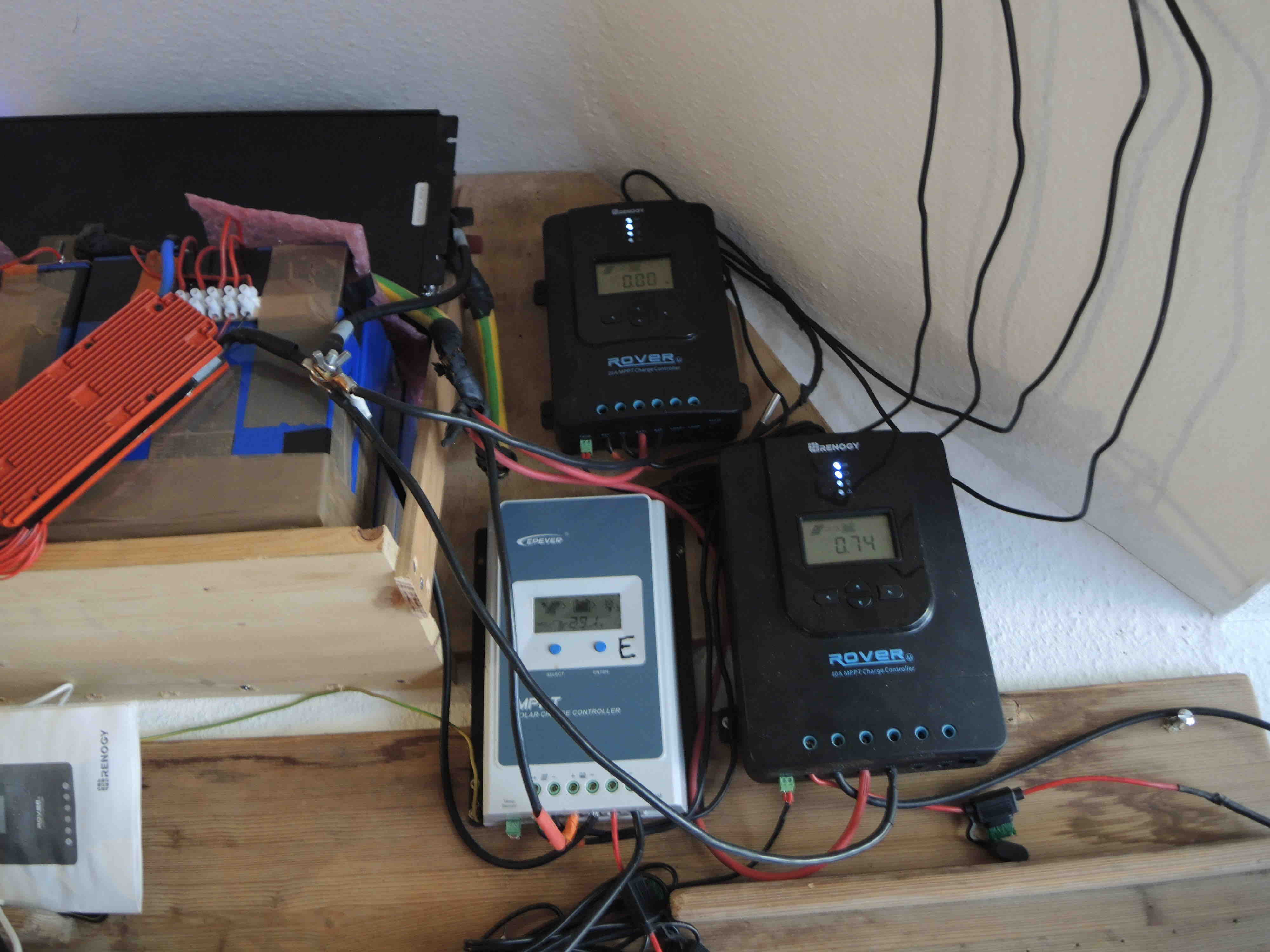
Mit dieser vorgehensweise fehlt dann auch nicht mehr viel, um den finalen schritt zu gehen:
- Jeden tag feststellen, wann die ladegeraete anfangen, die batterie zu fuettern
- Abwarten bis die batterie satt ist
- Waermepumpe einschalten und beobachten, wie viel strom sie bekommt
- Am abend, wenn die ladegeraete wieder schlafen gehen, die WP mit netzstrom nachfuettern, wenn noetig.
Ich habe soeben im datenblatt der WP nachgeschaut, was sie genau braucht: 425 W, 1.84 A bei 230 V. Die jaehrliche leistungsaufnahme haengt von der eintrittslufttemperatur ab und schwankt zwischen 1345 kWh bei 2 grad, 1069 kWh bei 14 grad und 1014 kWh bei 20 grad. Ich hole luft aus dem treppenhaus. Die hatte im vergangenen winter fast immer mindestens 16 grad. Wird sich natuerlich abkuehlen durch die WP. 1300 kWh / 365 Tage ergibt 3.5 kWh pro tag. Das ist aber fuer 300 Liter wasser oder mehr. Unser taeglicher verbrauch fuer 6 personen liegt bei ca. 150 liter/tag. Also muessten weniger als 2 kWh pro tag reichen, also 4 stunden sonne bei 425 W. bloederweise habe ich bei der PV-anlage mehr als 450 W zu verpulvern.
Daher waere es vielleicht optimal, nicht sofort zuerst ausschliesslich die batterie vollzuladen, sondern doch versuchen, gleich morgens frueh beides parallel anzutreiben, wenn genuegend sonne da ist.
Die batterie wird im sommer im laufe des tages auch dann voll, wenn die sonne nicht scheint. Nicht nur im sommer, sondern schon ab anfang februar.
Einspeisung
Direktvermarktung PV-Strom:
- 30Ct Einspeisevergütung statt 6Ct – so gehts!
- Operation Direktvermarktung – 10.000€ PV-Ertrag pro Jahr möglich?!
- Sonstige Direktvermarktung – eine lukrative Alternative?
- [22kWh LiFePo4 Akku für 3000€](https://youtu.be/FkUMFa8dd_0_
Foerderung
KfW-Bundesland Baden-Württemberg is running a Förderprogramm Netzdienliche Photovoltaik-Batteriespeicher supporting Stromspeicher in Verbindung mit neuer Photovoltaikanlage with a Zuschuss of 200 Euro pro kWh Speicherkapazität. Allerdings:
Aufgrund der hohen Nachfrage sind die Fördermittel leider erschöpft. Es können deshalb keine neuen Anträge mehr gestellt werden.
Our 24V battery stores 200 Ah or ca. 24 * 0.2 = 12 kWh, so we could have asked for 2400 Euro Zuschuss.
Battery Charge vs Consumption
Measurements comparing battery charge state with the kWh consumed in the 220 V AC circuit. Battery loss versus gain over day and power consumption over night:
| date time | E | S | V | kWh | h | ΔV | kWh |
| 2021-07-16 18:00 | 13.7 | 32.8 | |||||
| 2021-07-17 08:00 | 12.9 | 33.1 | 14 | 0.8 | 0.3 | ||
| 2021-07-17 17:50 | 14.3 | 33.5 | |||||
| 2021-07-18 06:30 | 12.8 | 34.0 | 13 | 1.5 | 0.5 | ||
| 2021-07-18 20:20 | 12.9 | 34.5 | |||||
| 2021-07-19 08:20 | 12.8 | 35.0 | 12 | 0.1 | 0.5 | ||
| 2021-07-19 20:20 | 0.0 | 59.9 | 13.0 | 35.5 | |||
| 2021-07-20 08:00 | 0.0 | 59.9 | 12.9 | 35.9 | 12 | 0.1 | 0.4 |
| 2021-07-20 14:00 | 0.8 | 60.2 | 14.2 | 36.2 | |||
| 2021-07-20 20:20 | 0.8 | 60.4 | 13.1 | 36.5 | |||
| 2021-07-21 07:20 | 0.8 | 60.4 | 12.8 | 36.9 | 11 | 0.3 | 0.4 |
Starting 2021-07-19 after installing the second charger for the roof ridge panels, I also added the total kWh produced by the two chargers attached to the four roof ridge panels facing east UE and the four balcony roof ones facing south US and started monitoring power generation and consumption from one morning to the next; UE, US, ΔE, ΔS and consumption C are in kWh per 24h.
| date time | UE | US | V | kWh | ΔE | ΔS | C |
| 2021-07-17 08:00 | 12.9 | 33.1 | |||||
| 2021-07-18 06:30 | 12.8 | 34.0 | 0.9 | ||||
| 2021-07-19 08:20 | 12.8 | 35.0 | 1.0 | ||||
| 2021-07-20 08:00 | 0.0 | 59.9 | 12.9 | 35.9 | 0.9 | ||
| 2021-07-21 07:20 | 0.8 | 60.4 | 12.8 | 36.9 | 0.8 | 0.5 | 1.0 |
| 2021-07-22 12:40 | 2.8 | 61.0 | 14.2 | 38.3 | |||
| 2021-07-22 20:10 | 3.1 | 61.1 | 13.1 | 38.7 | |||
| 2021-07-23 06:20 | 3.1 | 61.1 | 12.9 | 39.0 | 1.1 | 0.3 | 1.0 |
| 2021-07-24 08:00 | 4.2 | 61.4 | 12.8 | 40.1 | 1.1 | 0.3 | 1.1 |
| 2021-07-24 18:30 | 4.6 | 62.2 | 14.2 | 40.6 | |||
| 2021-07-24 23:40 | 4.6 | 62.2 | 12.8 | 41.2 | |||
| 2021-07-25 06:40 | 4.6 | 62.2 | 12.1 | off | |||
| 2021-07-25 10:40 | 4.6 | 62.2 | 12.4 | off |
ΔE is larger than ΔS. There may be several reasons for this: E probably receives more sun than S, since S is shadowed by the walnut tree. Also, E may already generate enough power to almost fully charge the battery, so S cannot add that much more afterwards.
Set up the 24 V system with new battery and new inverter on August 30; added voltage and amperage readings from different devices VE, AE, VS, AS, inverter VI and voltmeter on battery poles VB:
| date time | VE | AE | UE | VS | AS | US | VI | VB | kWh | ΔE | ΔS | C |
| 2021-08-30 15:00 | 9.1 | 67.1 | 27.3 | 44.8 | ||||||||
| 2021-08-30 18:00 | 9.1 | 67.3 | 27.3 | 44.9 | ||||||||
| 2021-08-31 06:40 | BMS blocked | |||||||||||
| 2021-08-31 08:40 | 9.1 | 67.3 | 26.4 | 45.4 | ||||||||
| 2021-08-31 20:40 | 9.5 | 68.1 | 26.5 | 46.1 | 0.4 | 0.8 | 1.2 | |||||
| 2021-09-01 08:20 | 9.5 | 68.1 | 26.4 | 46.6 | ||||||||
| 2021-09-01 21:40 | 10.3 | 68.8 | 26.5 | 47.3 | 0.8 | 0.7 | 1.2 | |||||
| 2021-09-01 23:10 | BMS blocked | |||||||||||
| 2021-09-02 09:30 | Fixed loose BMS C8+ sensor | |||||||||||
| 2021-09-02 09:30 | 10.3 | 68.8 | 26.5 | 83.9 | ||||||||
| 2021-09-02 20:10 | 10.9 | 69.0 | 26.6 | 84.3 | ||||||||
| 2021-09-03 09:00 | 10.9 | 69.0 | 26.3 | 84.9 | ||||||||
| 2021-09-03 10:00 | 26.4 | 11.0 | 26.3 | 69.0 | 26.5 | 25.8 | 85.0 | |||||
| 2021-09-03 12:10 | 27.1 | 7.7 | 11.5 | 27.1 | 8.6 | 69.1 | 27.2 | 26.5 | 85.1 | |||
| 2021-09-03 14:50 | 11.5 | 28.2 | 11.6 | 69.5 | 27.3 | 26.6 | 85.3 | |||||
| 2021-09-03 15:00 | 27.2 | -0.1 | 11.5 | 27.3 | 0.0 | 69.5 | 27.3 | 27.0 | 85.3 | |||
| 2021-09-03 16:40 | 28.1 | 0.1 | 11.8 | 27.3 | 0.0 | 69.6 | 27.3 | 27.0 | 85.3 | |||
| 2021-09-03 16:50 | 27.4 | -0.1 | 11.8 | 27.3 | 0.0 | 69.6 | 27.3 | 26.6 | 85.4 | |||
| 2021-09-03 20:10 | 26.4 | -0.1 | 11.8 | 26.4 | 0.0 | 69.7 | 26.5 | 25.9 | 85.6 | 0.9 | 0.7 | 1.3 |
| 2021-09-03 22:20 | 26.4 | -0.1 | 11.8 | 26.3 | 0.0 | 69.7 | 26.5 | 25.9 | 85.9 | 0.9 | 0.7 | 1.7 |
| 2021-09-04 09:10 | 26.3 | + 0.1 | 11.8 | 26.2 | 0.2 | 69.7 | 26.4 | 25.7 | 86.3 | |||
| 2021-09-04 13:30 | 27.3 | + 7.1 | 12.6 | 27.3 | 11.7 | 70.1 | 27.3 | 26.6 | 86.5 | |||
| 2021-09-04 15:30 | 27.1 | -0.1 | 12.7 | 27.4 | 0.0 | 70.3 | 27.5 | 26.7 | 86.6 | |||
| 2021-09-05 09:00 | 26.4 | + 0.1 | 12.7 | 26.3 | 0.1 | 70.4 | 26.4 | 25.8 | 87.2 | |||
| 2021-09-05 13:00 | 27.9 | + 3.2 | 13.4 | 27.9 | 11.2 | 70.7 | 28.3 | 27.4 | 87.4 | |||
| 2021-09-05 16:10 | 27.6 | -0.1 | 13.4 | 27.4 | 0.0 | 70.8 | 27.5 | 26.9 | 87.5 | |||
| 2021-09-05 21:00 | 26.4 | -0.1 | 13.4 | 26.3 | 0.0 | 70.9 | 26.5 | 25.8 | 87.8 | |||
| 2021-09-06 07:30 | 26.3 | -0.1 | 13.4 | 26.3 | 0.0 | 70.9 | 26.4 | 25.8 | 88.3 | |||
| 2021-09-06 12:40 | 27.4 | + 8.1 | 14.0 | 27.4 | 10.8 | 71.0 | 27.5 | 26.7 | 88.5 | |||
| 2021-09-06 17:20 | 27.9 | + 0.1 | 14.2 | 27.9 | 5.0 | 71.5 | 28.0 | 27.4 | 88.8 | |||
| 2021-09-06 19:30 | 26.5 | + 0.0 | 14.2 | 26.4 | 0.0 | 71.6 | 26.6 | 25.9 | 88.9 | |||
| 2021-09-06 21:00 | 26.5 | -0.0 | 14.2 | 26.4 | 0.0 | 71.6 | 26.6 | 25.9 | 89.0 | |||
| 2021-09-07 09:10 | 26.5 | + 0.2 | 14.2 | 26.4 | 0.3 | 71.6 | 26.6 | 25.9 | 89.5 | |||
| 2021-09-07 13:40 | 27.5 | + 6.8 | 14.9 | 27.5 | 11.3 | 72.1 | 27.6 | 26.8 | 89.5 | |||
| 2021-09-07 17:40 | 26.9 | + 0.1 | 14.9 | 26.8 | 0.9 | 72.3 | 26.9 | 26.3 | 90.0 | |||
| 2021-09-08 06:50 | 26.5 | -0.1 | 15.0 | 26.4 | 0.0 | 72.3 | 26.6 | 26.3 | 90.5 | |||
| 2021-09-08 12:00 | 27.1 | + 8.3 | 15.3 | 26.9 | 1.3 | 72.4 | 27.0 | 26.4 | 90.8 | |||
| 2021-09-08 20:20 | 26.5 | -0.1 | 15.7 | 25.9 | 0.0 | 72.9 | 26.6 | 26.4 | 91.1 | |||
| 2021-09-09 08:00 | 26.4 | + 0.0 | 15.7 | 26.3 | 0.2 | 72.9 | 26.5 | 25.8 | 91.7 | |||
| 2021-09-09 10:00 | 26.6 | + 5.5 | 15.8 | 26.5 | 0.4 | 73.0 | 26.7 | 26.0 | 91.9 | |||
| 2021-09-09 12:20 | 27.0 | + 3.4 | 16.1 | 27.0 | 4.4 | 73.0 | 27.2 | 26.6 | 92.0 | |||
| 2021-09-09 20:30 | 26.5 | -0.1 | 16.5 | 26.4 | 0.0 | 73.7 | 26.6 | 26.2 | 92.3 | |||
| 2021-09-10 08:10 | 26.5 | 0.0 | 16.5 | 26.4 | 0.1 | 73.7 | 26.5 | 26.2 | 92.8 | |||
| 2021-09-10 12:20 | 27.0 | 4.6 | 16.7 | 27.0 | 5.9 | 73.9 | 27.1 | 26.7 | 93.2 | |||
| 2021-09-10 22:40 | 27.0 | 0.0 | 17.0 | 27.0 | 0.0 | 74.4 | 26.5 | 26.2 | 93.9 | |||
| 2021-09-11 08:30 | 26.4 | 0.2 | 17.0 | 26.4 | 0.3 | 74.4 | 26.5 | 26.1 | 94.3 | |||
| 2021-09-11 12:50 | 26.8 | 3.0 | 17.3 | 26.7 | 3.9 | 74.6 | 26.8 | 26.4 | 94.7 | |||
| 2021-09-11 21:50 | 25.3 | 0.1 | 17.4 | 25.2 | 0.0 | 75.2 | 26.4 | 95.3 | ||||
| 2021-09-12 09:20 | 25.2 | 0.1 | 17.4 | 25.2 | 0.1 | 75.2 | 26.3 | 95.8 | ||||
| 2021-09-12 11:00 | 26.6 | 8.7 | 17.5 | 26.5 | 0.2 | 75.2 | 26.5 | 26.2 | 95.9 | |||
| 2021-09-12 12:20 | 26.9 | 3.5 | 17.8 | 26.7 | 3.7 | 75.7 | 26.8 | 26.4 | 96.0 | |||
| 2021-09-12 16:30 | 27.4 | 1.2 | 18.5 | 27.4 | 11.8 | 76.6 | 26.8 | 27.1 | 96.2 | |||
| 2021-09-13 08:00 | 0.0 | 18.5 | 25.4 | 0.0 | 76.7 | 25.3 | 25.2 | 96.8 | ||||
| 2021-09-13 12:40 | 27.4 | 8.0 | 19.0 | 27.3 | 10.8 | 76.8 | 27.4 | 26.9 | 97.0 | |||
| 2021-09-13 16:20 | 27.2 | -0.1 | 19.3 | 27.5 | 0.0 | 77.3 | 27.3 | 27.3 | 97.3 | |||
| 2021-09-13 22:10 | 26.5 | -0.1 | 19.3 | 26.4 | 0.0 | 77.4 | 26.6 | 26.2 | 97.6 | |||
| 2021-09-14 08:10 | 26.5 | + 0.1 | 19.3 | 26.4 | 0.1 | 77.4 | 26.6 | 26.2 | 97.9 | |||
| 2021-09-14 11:00 | 26.5 | + 3.4 | 19.4 | 26.4 | 0.5 | 77.4 | 26.6 | 26.2 | 98.3 | |||
| 2021-09-14 12:10 | 27.0 | + 8.1 | 19.5 | 26.9 | 2.8 | 77.4 | 26.9 | 26.6 | 98.4 | |||
| 2021-09-14 22:20 | 26.4 | -0.1 | 19.9 | 26.3 | 0.0 | 77.9 | 26.4 | 26.1 | 98.8 | |||
| 2021-09-15 11:40 | 26.4 | + 0.1 | 19.9 | 26.3 | 0.2 | 77.9 | 26.5 | 26.1 | 99.5 | |||
| 2021-09-15 20:00 | 26.1 | -0.1 | 20.0 | 26.0 | 0.0 | 78.1 | 26.2 | 25.8 | 100.0 | |||
| 2021-09-16 15:20 | 26.8 | + 3.6 | 20.3 | 26.8 | 11.0 | 78.8 | 26.9 | 26.4 | 101.1 | |||
| 2021-09-16 20:10 | 26.3 | -0.1 | 20.4 | 26.2 | 0.0 | 79.3 | 26.3 | 26.0 | 101.4 | |||
| 2021-09-17 08:50 | 26.0 | 0.1 | 20.4 | 25.9 | 0.2 | 79.3 | 26.0 | 25.7 | 101.9 | |||
| 2021-09-17 12:00 | 27.0 | 8.1 | 20.8 | 26.9 | 5.4 | 79.4 | 27.0 | 26.7 | 102.1 | |||
| 2021-09-18 09:20 | 26.4 | 0.1 | 21.4 | 26.3 | 0.1 | 80.9 | 26.5 | 26.1 | 102.9 | |||
| 2021-09-18 15:50 | 27.7 | -0.1 | 22.2 | 27.6 | 3.8 | 81.8 | 27.7 | 26.1 | 103.2 | |||
| 2021-09-18 19:50 | 26.6 | -0.1 | 22.2 | 26.5 | 0.0 | 81.9 | 27.6 | 26.3 | 103.4 | |||
| 2021-09-19 09:30 | 26.4 | 0.0 | 22.2 | 26.3 | 0.1 | 81.9 | 26.4 | 26.1 | 104.2 | |||
| 2021-09-19 21:50 | 26.1 | 0.0 | 22.3 | 26.0 | 0.1 | 81.9 | 26.1 | 25.8 | 104.7 | |||
| 2021-09-20 11:50 | 26.3 | 0.4 | 22.3 | 26.3 | 1.8 | 82.0 | 26.4 | 26.0 | 105.3 | |||
| 2021-09-20 22:20 | 25.9 | -0.0 | 22.5 | 25.8 | 0.0 | 82.5 | 25.9 | 25.6 | 106.0 | |||
| 2021-09-21 09:00 | 25.9 | -0.0 | 22.5 | 25.8 | 0.1 | 82.5 | 25.9 | 25.8 | 106.3 | |||
| 2021-09-21 19:50 | 26.1 | -0.1 | 23.0 | 26.0 | 0.0 | 83.7 | 26.2 | 25.9 | 106.9 | |||
| 2021-09-22 21:00 | 26.4 | -0.1 | 23.9 | 26.3 | 0.0 | 85.0 | 26.4 | 25.9 | 108.2 | |||
| 2021-09-23 09:20 | 26.1 | 0.0 | 23.9 | 26.0 | 0.1 | 85.0 | 26.2 | 25.8 | 108.6 | |||
| 2021-09-23 12:50 | 27.3 | 8.0 | 24.4 | 27.2 | 11.2 | 85.3 | 27.2 | 26.8 | 108.7 | |||
| 2021-09-24 08:10 | 26.5 | -0.1 | 24.8 | 26.4 | 0.0 | 86.5 | 26.5 | 26.2 | 109.5 | |||
| 2021-09-24 11:50 | 27.2 | 8.6 | 25.1 | 27.1 | 4.6 | 86.5 | 27.2 | 26.9 | 109.8 | |||
| 2021-09-27 09:50 | 26.3 | 0.1 | 26.3 | 26.3 | 0.2 | 88.4 | 26.4 | 26.1 | 112.5 | |||
| 2021-10-02 12:40 | 27.0 | 3.8 | 29.0 | 26.9 | 5.1 | 91.9 | 27.0 | 26.6 | 116.6 | |||
| 2021-10-03 21:50 | 25.9 | 0.0 | 29.4 | 25.8 | 0.0 | 92.6 | 25.9 | 25.6 | 118.9 | |||
| 2021-10-04 08:20 | 25.7 | 119.5 | ||||||||||
| 2021-10-05 19:10 | 25.7 | 0.0 | 29.4 | 25.7 | 0.0 | 92.7 | 25.7 | 25.4 | 119.9 | |||
| 36-day total | 20.3 | 25.6 | 38.5 | |||||||||
| 1-day average | 0.56 | 0.71 | 1.07 | |||||||||
While the battery was blocked in the night between September 1-2, the consumption meter jumped from 47.3 to 83.9 kWh, so deduct 36.6 from the total consumption.
The sun shone almost uninterrupted every day all day September 1-5, so the batteries should reach 100% SOC (or whatever maximum charge is desired) if everything is working correctly.
September 3: With the chargers charging slightly at 10 o’clock in the morning, producing 0.1-0.2 A each, the different devices, chargers S, E, inverter I and voltmeter on battery poles B report the following voltages:
| date time | E | S | I | B |
| 2021-09-03 10:00 | 26.4 | 26.3 | 26.5 | 25.8 |
On September 3 just before three in the afternoon, VE and AE, VS dropped from 28.2 · 11.6 down to 27.3 · 0.0 within a minute or so. Why? Was that the switch from boost charging to float charging? Should I raise the boost charging time to increate the battery state of charge SOC?
Later the same day, just before five, VS and AS dropped from 28.2 · + 0.1 down to 27.4 · -0.1; also to stop charging because a limit was hit, I assume.
The battery pole voltage is still just 26.6 as soon as charging has stopped.
I raised the boost duration from 120 to 180. I want to raise the battery ‘fully charged’ level up to 28 V at least, preferably 29. On the other hand, a resting voltage below 25 V is getting low and above 26.8 V is nearly full. So, maybe I am in a pretty good window now.
In the evening of September 3, we watched TV and consumed 0.4 kWh. The battery pole voltage remained unchanged at 25.9 V, so all seems to be well.
2021-09-06: During the night, the battery lost 0.1 V going from 25.9 to 25.8 to give out 0.8 kWh; pretty good going.
2021-09-06: Raised float charging voltage from 27.6 to 28, and boost reconnect charging voltage from 26.4 to 26.8 V, trying to achieve a resting battery pole voltage in the evening and night above 26 V. So far, the BMS has always shown at least 0.6 V higher voltage to the charger than the battery pole voltage.
2021-09-06: Watched the float charging video and modified the float charging voltage to equal the absorbtion or boost one, setting both to 29 V. Raised the boost charge reconnect voltage to 27 V, Also reduced the equalisation duration to zero; it should be disabled anyway: east, south.
2021-09-07: i-tecc says about the BMS:
Q: Egal ob tagsueber geladen + verbraucht wird oder nachts nur verbraucht ist Vp immer etwas hoeher als Vb, um ca. 0.6 bis 0.9 V. Ist das normal?
A: Nein. Es könnte ein Anschlussfehler vorliegen oder die Verbindung nicht richtig sitzen. Wir würden empfehlen zu untersuchen, woher die Differenz kommt.
Q: Ich will gerne die batterie bis ca. 27 V volladen. Ich will sie gar nicht bis zur grenze von 29.2 vollpumpen. Ich habe gelesen, dass die batterie schon bei 26.8 V als fast voll betrachtet werden kann.
A: Die Ladeschlussspannung liegt bei 28.8V.
29.2V wäre zu hoch, alles unter 28.8V ist zu niedrig, um ein ausgeglichenes System zu erhalten.
Sie brauchen die 3.6V pro Einzelzelle, damit der Balancer arbeiten kann.
Sie können gerne ab und zu die Batterie nur mit 27V laden, allerdings sollten die 28.8V auch regelmässig erreicht werden, gerade in der Anfangsphase/Initialladung.
So, I upped the charger boost and float charging voltages from 29 to 29.5 V to hopefully ensure the battery pole voltages reach 28.8 soon: east, south. This forced me to raise the charging limit voltage to a higher value; I picked 29.6 V for that.
2021-09-08: One little puzzle solved: my digital voltmeter reports 0.6 V less than the inverter readout, so the observed difference so far between battery minus and BMS minus poles is actually and always has been non-existant. So, I am assuming that VB is the more accurate measurement, and all the others are too high.
Some success raising the SOC: for the first time, the battery pole voltage is over 26 V in the early morning, before charging starts.
2021-09-13: at 16:25, the battery voltage is 27.3 and the south panels are in full sunshine. Yet, the charger reports zero ampere charging current. Apparently, it has switched off. Why? Did it possibly switch off because the bulk charging time is limited to 180 minutes?
2021-09-14: epever provided new recommended settings, so i updated east and south.
2021-10-02: returned from a week’s absence in ticino, battery full, over 26.6 V. used lots ofg power for lightin, broken pc screen, everythin pluged in all the time.
2021-10-04: rained all day yesterday and today, no sunshoine, battery rather low, under 25 V, lights started flickering, turning on and off. cbl turned off the inverter. in the evening, i turned it on again. after a while, the bms switched off, probably due to unbalanced cells. the battery was at 24.4 V, i think. we switched to mains electricity and took down the battery to charge it above 28.8 for the bms to balance the cells. solar pause.
2021-10-20: charging the entire chain of cells failed due to imbalanced cells, the bms blocks. total voltage 26.2 V, individual cell voltages:
- 3.29
- 3.27
- 3.29
- 3.29
- 3.29
- 3.29
- 3.29
- 3.29
Started charging cell 2 with 3.3 V at 1 A at 2021-10-20 12:50. It only took half an hour or so to et it up to 3.29 V.
Added luster terminals to enable charging individual cells.
Attached the battery to the chargers and inverter again.
| date time | UE | AE | US | AS | VI | VB | kWh | ΔE | ΔS | C |
| 2021-10-20 17:40 | 29.4 | -0.1 | 92.7 | 0.1 | 26.7 | 26.2 | 120.1 | |||
| 2021-10-21 08:50 | 29.4 | 0.0 | 92.7 | 0.2 | 26.4 | 25.9 | 120.8 | |||
| 2021-10-21 12:10 | 29.5 | 0.6 | 92.8 | 4.0 | 26.8 | 26.1 | 121.0 | |||
| 2021-10-21 23:10 | 29.7 | 0.0 | 93.6 | 0.0 | 26.4 | 25.8 | 121.4 | |||
| 2021-10-22 11:50 | 29.7 | 0.3 | 93.6 | 0.5 | 26.4 | 25.7 | 121.9 | |||
| 2021-10-22 24:00 | 30.2 | 0.0 | 95.0 | 0.0 | 26.5 | 25.8 | 123.2 | |||
| 2021-10-23 08:00 | 30.2 | 0.0 | 95.0 | 0.0 | 26.3 | 25.6 | 123.5 | |||
| 2021-10-23 12:00 | 30.4 | 8.0 | 95.1 | 8.5 | 26.9 | 26.2 | 123.9 | |||
| 2021-10-24 09:30 | 30.9 | 0.0 | 96.4 | 0.0 | 26.4 | 25.7 | 124.8 | |||
| 2021-10-24 12:10 | 31.1 | 8.3 | 96.5 | 9.2 | 27.1 | 26.4 | 125.1 | |||
| 2021-10-24 14:00 | 31.5 | 5.6 | 97.1 | 12.5 | 27.3 | 26.5 | 125.3 | |||
| 2021-10-24 22:30 | 31.6 | 0.0 | 97.5 | 0.0 | 26.5 | 25.8 | 125.8 | |||
| 2021-10-25 09:00 | 31.6 | 0.1 | 97.5 | 0.0 | 26.4 | 25.7 | 126.2 | |||
| 2021-10-25 13:50 | 32.1 | 5.6 | 98.1 | 11.5 | 27.2 | 26.4 | 126.7 | |||
| 2021-10-25 17:40 | 32.2 | 0.0 | 98.5 | 0.1 | 26.6 | 25.9 | 126.9 | |||
| 2021-10-26 08:40 | 32.2 | 0.1 | 98.5 | 0.1 | 26.2 | 25.6 | 128.1 | |||
| 2021-10-27 07:50 | 32.4 | 0.0 | 98.9 | 0.0 | 25.8 | 25.2 | 130.0 | |||
| 2021-10-27 16:10 | 33.0 | 0.0 | 100 | 9.1 | 26.7 | 26.0 | 130.7 | |||
| 2021-10-27 18:30 | 33.0 | 0.0 | 100 | 0.0 | 26.3 | 25.6 | 130.8 | |||
| 2021-10-28 08:00 | 33.0 | 0.0 | 100 | 0.0 | 25.7 | 25.3 | 131.7 | |||
| 2021-10-28 12:20 | 33.3 | 7.3 | 101 | 10.0 | 26.5 | 25.8 | 132.2 | |||
| 2021-10-28 14:20 | 33.6 | 4.6 | 101 | 12.3 | 26.8 | 26.1 | 132.3 | |||
| 2021-10-28 16:10 | 33.7 | 0.1 | 102 | 9.1 | 26.8 | 26.0 | 132.4 | |||
| 2021-10-28 20:00 | 33.7 | 0.0 | 102 | 0.0 | 26.2 | 25.5 | 132.7 | |||
| 2021-10-29 11:30 | 33.7 | 0.9 | 102 | 1.9 | 25.9 | 25.2 | 133.7 | |||
| 2021-10-29 12:30 | 33.9 | 6.7 | 102 | 9.2 | 26.6 | 25.9 | 133.8 | |||
| 2021-10-29 14:10 | 34.2 | 4.6 | 103 | 11.8 | 26.8 | 26.1 | 133.9 | |||
| 2021-10-29 18:00 | 34.3 | 0.0 | 103 | 0.0 | 26.3 | 25.8 | 134.3 | |||
| 2021-10-30 08:00 | 34.3 | 0.0 | 103 | 0.0 | – | 25.0 | – |
2021-10-30 08:00: the central heating was running all night. battery cells unbalanced again, and the bms started flickering on and off. total voltage 25.0 V. individual cell voltages:
- 3.18
- 2.65
- 3.18
- 3.17
- 3.22
- 3.22
- 3.24
- 3.23
2021-10-31 20:30: after two day with no load, the battery is back up to 26.1 V, and all cells appear balanced at 3.27 V.
2021-11-02 20:30, 2021-11-03 17:30, 2021-11-05 12:00: two + three more days with no load and little sunshine: 26.3 V, cells unbalanced at:
- 3.29 3.30 3.32
- 3.27 3.27 3.27
- 3.28 3.28 3.32
- 3.28 3.28 3.32
- 3.31 3.31 3.34
- 3.31 3.31 3.34
- 3.31 3.31 3.34
- 3.31 3.31 3.34
Strange… two blocks of four, it seems…
2021-11-06 08:00 bms: shut off again with inverter saying 25.3 V, presumably due to imbalanced cells. anette was viting last night and sr=tayed the night and probably left her laptop plugged in, using more than expected.
2021-11-12 17:50: several foggy days. i switched to mains overnight, or as soon as the inverter showed less than 26 V, corresponding to about 25.3 V, measured by voltmeter on the battery. the battery continued charging, but very slowly, of course. in the week nov. 5-12, the chargers report 2 + 5 = 7 kWh net gain, the consumption is 4.4 kWh, and the battery voltage rose from 25.4 to 24.7 V. does that 0.3 V rise correspond to 2.6 kWh more energy stored? or do we need to take a large loss of energy into account, consumed energy being much less than the energy produced by the chargers? 19:30: battery voltage is down to 26.0 V and 25.4 V, resp., and consumption up to 142.1, so only 0.2 kWh. so it seems that the charger report uch more power produced than we actually consume: 7 versus 4.6 kWh, 66% or only ca. efficiency.
2021-11-18: turned it on again on a sunny day after a series of very cloudy ones. the battery was almost as low as when i stopped using solar power, even though the chargers report having generated some energy in the meantime. turned it off again in the evening at 19:30.
2021-11-19: turned it on again at 08:40 for another sunny day.
2021-11-20 15:40 in full sunshine: the inverter battery voltage 27.7 V, 26.7 at the bms battery poles, both panels were in full sunshine, east panels 80 V, south 91, yet both of them charging 0 A. why do they both stop charging at a voltage below 28 V?
2021-11-21 17:40 turned off solar again after a completely foggy day with zero input. we lasted only 24 hours, even though the battery was so full yesterday that the charger stopped charging. we used only 1.2 kWh during that time… where are the 4.8 kWh that the battery is theoretically able to store?
2021-11-23 21:40 the sun shone quite a lot today, and i switched from mains back to solar quite early in the morning.
i compared my voltmeter with cbl. mine seems to be consistently showing too low values, so all the VB measurements so far are wrong, too low, and the VI ones are correct.
2021-11-29 10:10 cbl turned off solar power last week wednesday ro thursday and the sun was away for several days. today, and i switched from mains back to solar. VB was 25.9 before turning on the inverter, 25.5 afterwards.
2021-12-02 18:20 been raining nonstop for a couple of days, inverter switched off. starting to hook up cbl used panels directly to the battery. measured the cells to check and potentially balance the bad one.
2021-12-03 10:40 sun is shining, finally switched from mains to pv again.
2021-12-15 Started attaching cbl used PV panels directly to the battery, in pairs, each providing 230 Wp, 4.7 A short circuit, 65.4 V open circuit, limited by the battery + BMS + inverter to 29 V, so they will never be able to provide more than max. 130 W per pair…
Monitoring individual cells; voltages until november were measured with my faulty voltmeter reporting too low values; from december onwards using cbl voltmeter; oh no, it does not measure with any precision below 0.1 V, so it makes little sense in this range:
Meter Readings 2022
2022-01-05 After disconneting the burned inverter and having no load for a while, the battery ought to be full, and over 28.8 V, and the BMS ought to be actively balancing.
| date time | 1 | 2 | 3 | 4 | 5 | 6 | 7 | 8 | notes |
| 2021-10-30 08:00 | 3.18 | 2.65 | 3.18 | 3.17 | 3.22 | 3.22 | 3.24 | 3.23 | bms turned off |
| 2021-10-31 20:30 | 3.27 | 3.27 | 3.27 | 3.27 | 3.27 | 3.27 | 3.27 | 3.27 | after 2 days charging with no load |
| 2021-11-02 20:30 | 3.29 | 3.27 | 3.28 | 3.28 | 3.31 | 3.31 | 3.31 | 3.31 | cell 2 lags, cells 4-8 are ahead |
| 2021-11-03 17:30 | 3.30 | 3.27 | 3.28 | 3.28 | 3.31 | 3.31 | 3.31 | 3.31 | |
| 2021-11-05 12:00 | 3.32 | 3.27 | 3.32 | 3.32 | 3.34 | 3.34 | 3.34 | 3.34 | during charging ca. 5 A |
| 2021-12-02 18:20 | 3.25 | 3.19 | 3.24 | 3.21 | 3.27 | 3.27 | 3.27 | 3.26 | not charging |
| 2021-12-16 17:20 | 3.21 | 3.20 | 3.20 | 3.20 | 3.21 | 3.21 | 3.21 | 3.21 | not charging |
| 2021-12-16 19:20 | 3.20 | 3.18 | 3.20 | 3.20 | 3.20 | 3.20 | 3.20 | 3.20 | after consuming ca. 0.3 kWh |
| 2021-12-16 21:00 | 3.20 | 3.16 | 3.19 | 3.18 | 3.20 | 3.20 | 3.20 | 3.20 | after consuming ca. 0.5 kWh |
| 2022-01-05 14:00 | 3.32 | 3.32 | 3.32 | 3.32 | 3.77 | 3.77 | 3.64 | 3.33 | bms stops charging further at 27.7 V |
| 2022-01-06 08:00 | 3.30 | 3.30 | 3.30 | 3.30 | 3.30 | 3.30 | 3.30 | 3.30 |
On 2022-01-06, I disconnected the battery and started charging the individual cells. The BMS manufacturer i-tecc states that the BMS will balance the cells above 28.8 V, so each individual cell ought to be at 3.51 V.
| date time | UE | AE | US | AS | VI | VB | kWh | ΔE | ΔS | C |
| 2021-10-31 20:30 | 34.9 | 0.0 | 104 | 0.0 | – | 26.1 | – | |||
| 2021-11-02 20:30 | 35.0 | 0.0 | 105 | 0.0 | – | 26.3 | – | |||
| 2021-11-03 17:30 | 35.1 | 0.0 | 105 | 0.0 | – | 26.3 | – | |||
| 2021-11-04 19:50 | 35.1 | 0.0 | 105 | 0.0 | 26.1 | 25.5 | 136.7 | |||
| 2021-11-05 08:40 | 35.1 | 0.0 | 105 | 0.1 | 26.1 | 25.4 | 137.1 | |||
| 2021-11-05 12:00 | 35.1 | 3.0 | 105 | 4.9 | 26.5 | 25.7 | 137.2 | |||
| 2021-11-05 18:00 | 35.3 | 0.0 | 105 | 0.0 | 26.2 | 25.4 | 137.5 | |||
| 2021-11-12 17:50 | 37.3 | 0.0 | 110 | 0.0 | 26.4 | 25.7 | 141.9 | |||
| 2021-11-12 19:30 | 37.3 | 0.0 | 110 | 0.0 | 26.0 | 25.4 | 142.1 | |||
| 2021-11-18 08:40 | 37.4 | 0.1 | 110 | 0.1 | 26.3 | 142.1 | ||||
| 2021-11-18 16:00 | 37.8 | 0.0 | 111 | 0.3 | 26.6 | 25.9 | 142.4 | |||
| 2021-11-18 18:40 | 37.8 | 0.0 | 111 | 0.0 | 26.4 | 25.7 | 142.5 | |||
| 2021-11-19 08:40 | 37.8 | 0.0 | 111 | 0.0 | 26.6 | 25.9 | 142.6 | |||
| 2021-11-19 10:40 | 37.8 | 2.3 | 111 | 0.3 | 26.7 | 25.8 | 142.7 | |||
| 2021-11-19 19:30 | 38.2 | 0.0 | 112 | 0.0 | 26.6 | 25.8 | 142.9 | |||
| 2021-11-20 10:40 | 38.2 | 0.3 | 112 | 0.6 | 26.7 | 25.9 | 143.0 | |||
| 2021-11-20 15:40 | 38.3 | 0.0 | 112 | 0.0 | 27.7 | 26.7 | 143.1 | |||
| 2021-11-20 18:40 | 38.3 | 0.0 | 112 | 0.6 | 26.5 | 25.8 | 143.3 | |||
| 2021-11-21 09:20 | 38.3 | 0.1 | 112 | 0.2 | 26.5 | 25.7 | 143.8 | |||
| 2021-11-21 17:40 | 38.3 | 0.0 | 112 | 0.2 | 26.2 | 25.5 | 144.4 | |||
| 2021-11-23 15:20 | 38.7 | 0.0 | 113 | 0.3 | 26.9 | 26.1 | 144.5 | |||
| 2021-11-23 21:40 | 38.7 | 0.0 | 113 | 0.0 | 26.5 | 25.7 | 144.9 | |||
| 2021-11-24 05:40 | 38.7 | 0.0 | 113 | 0.0 | 26.4 | 25.7 | 145.1 | |||
| 2021-11-24 11:00 | 38.7 | 0.1 | 113 | 0.4 | 26.4 | 25.7 | 145.3 | |||
| 2021-11-29 10:10 | *25.9 | |||||||||
| 2021-11-29 10:10 | 38.9 | 0.4 | 114 | 0.5 | 26.2 | 25.5 | 147.2 | |||
| 2021-11-29 11:10 | 38.9 | 0.6 | 114 | 0.7 | 25.8 | 25.0 | 147.3 | |||
| 2021-11-30 15:00 | 38.9 | 0.0 | 114 | 0.0 | 25.8 | 25.1 | 147.4 | |||
| 2021-12-01 17:00 | 25.8 | |||||||||
| 2021-12-02 18:20 | 25.9 | |||||||||
| 2021-12-03 10:40 | 39.0 | 0.8 | 114 | 0.7 | 26.3 | 25.6 | 147.4 | |||
| 2021-12-03 18:40 | 39.3 | 0.0 | 114 | 0.8 | 26.2 | 25.5 | 147.6 | |||
| 2021-12-07 10:50 | 26.3 | |||||||||
| 2021-12-07 11:00 | 39.4 | 0.7 | 115 | 0.2 | 26.6 | 25.8 | 147.6 | |||
| 2021-12-07 20:00 | 39.7 | 0.0 | 115 | 0.0 | 26.1 | 25.5 | 148.3 | |||
| 2021-12-12 10:10 | 26.5 | |||||||||
| 2021-12-12 10:20 | 39.8 | 1.7 | 116 | 2.2 | 26.1 | 26.0 | 148.3 | |||
| 2021-12-13 10:00 | 26.3 | |||||||||
| 2021-12-13 10:10 | 39.9 | 1.1 | 116 | 0.9 | 26.6 | 25.8 | 148.7 | |||
| 2021-12-13 14:00 | 40.3 | 0.4 | 116 | 2.5 | 26.8 | 26.0 | 148.8 | |||
| 2021-12-13 18:10 | 40.3 | 0.0 | 117 | 0.0 | 26.5 | 25.8 | 149.1 | |||
| 2021-12-14 06:40 | 40.3 | 0.0 | 117 | 0.0 | 26.3 | 25.5 | 149.7 | |||
| 2021-12-14 22:20 | 40.6 | 0.0 | 117 | 0.0 | 26.3 | 25.6 | 150.4 | |||
| 2021-12-16 09:50 | 40.6 | 0.1 | 117 | 0.3 | 26.4 | 26.0 | 150.6 | |||
| 2021-12-16 17:10 | 40.6 | 0.0 | 118 | 0.0 | 26.1 | 25.7 | 150.8 | |||
| 2021-12-16 19:20 | 40.6 | 0.0 | 118 | 0.0 | 25.9 | 25.5 | 151.1 | |||
| 2021-12-16 20:50 | 40.6 | 0.0 | 118 | 0.0 | 26.0 | 25.5 | 151.3 | |||
| 2021-12-17 10:30 | 40.6 | 0.0 | 118 | 0.2 | 26.3 | 25.8 | 151.4 | |||
| 2021-12-17 20:20 | 40.7 | 0.0 | 118 | 0.0 | 25.7 | 25.2 | 151.9 | |||
| 2021-12-18 08:40 | 40.7 | 0.0 | 118 | 0.0 | 26.1 | 25.6 | 151.9 | |||
| 2021-12-18 12:50 | 40.9 | 4.4 | 118 | 9.8 | 27.0 | 26.4 | 152.1 |
2022-01-19: hooked up the new balancer. beforehand, battery cell voltages were 3.3, 3.3, 3.3, 3.3, 3.3, 3.34, 3.3, 3.3. total compumption so far 152.8 kWh.
2022-01-28: installed the new PUGU inverter and started using solar power again. before connecting the inverter, the battery cells seemed extremely badly balanced in spite of the active balancer connected, with #3 very high and #4 very low. total voltage started out at 28.2 V and rapidly dimished. after a couple of minutes of use they evened out somewhat: 3.32, 3.32, 3.44, 3.29, 3.29, 3.31, 3.31, total voltage 27.7 V, total kWh consumption at 152.8.
2022-01-29 20:10: 153.3 kWh, VI 27.1 V; inverter failed and switched off at 01:00 o’clock in the night.
2022-01-30 10:10: sunshine, 153.8 kWh, VI 27.9 V
2022-01-30 18:10: dark, 153.9 kWh, VI 27.3 V, VS 26.3 V, 120 kWh, VE 26.4 V, 41.9 kWh
2022-01-31 10:40: very cloudy, 154.0 kWh, VI 26.4 V, VS 26.6 V, 121 kWh, VE 26.7 V, 42.0 kWh, bms blocking intermittently, 3.31, 3.31, 3.30, 3.30, 3.49, 3.31, 3.31, 3.31 balancer is not working! five minutes later, things look ok, bms unblocked, inverter works again…
2022-02-03 13:20: new daly bms installed, balancer and i-tecc bms removed, up and running again.
C 154.0 kWh, Vb 26.4, all cells at 3.3 V;
22:00 154.4 kWh 26.3 Vs
2022-02-04 08:40: hooked up east epever charger again; C 154.7 kWh, E 42.1 kWh 26.3 V, S 121 kWh 26.1 V
2022-02-05 14:30: rover charger installed, sunny: C 155.5 kWh, E 42.6 kWh 29.1 V, -0.1 A, S 122 kWh 29.0 V 0.7 A, V 28.7 V 40 V 7.5 A 30 Ah; 17:50 C 155.7 E 42.6 26.5 S 122 26.4 V 26.2V 33 Ah
2022-02-06 10:50: C 156.5 E 42.6 26.7 S 122 26.6 V 26.4V 5 Ah
2022-02-07 17:20: C 157.8 E 43.2 26.5 S 123 26.4 V 26.3V 45 Ah: kWh diff: C 1.3 E 0.4 S 1.0 V 1.0
2022-02-08 03:30: C 158.2 E 43.2 26.5 S 123 26.4 V 26.3V 45 Ah
2022-02-08 07:20: C 158.3 E 43.2 26.4 S 123 26.3 V 26.2V 45 Ah
2022-02-08 12:20: C 158.6 E 43.6 27.5V 7A S 124 28.8V 5.4A V 27.2V 11Ah
2022-02-08 20:00: C 159.1 E 43.6 26.5V 0A S 124 26.4V 0.0A V 26.2V 23Ah
2022-02-09 12:40: C 160.4 before running washing machine for the first time in full sunshine: it uses ca. 2100 W for some short periods of time; battery fully loaded with 29V before starting, suddenly sinking to 25.5V when fully loaded; charging during run: E 76V 1.3A 25.6V 3A S 44V 10A 25.3V V 63V 4.7A 26.7V 12A
2022-02-09 19:30: C 161.5 E 44.3 26.4V 0A S 125 26.3V 0.0A V 26.1V 47Ah; diff: C 2.4 E 0.7 S 1 V 1.2 sum 2.9
2022-02-10 midday: C 162.9 before running washing machine with a 60 degree load for the second time in full sunshine: battery not fully loaded before starting, but pretty full, suddenly sinking from ca. 27V to ca. 26V; charging during run: E 26.2V 6.8A S 27.1V 10.7A V 47V 13A C 164.1 after washing run.
2022-02-10 18:20: C 164.4 E 45.0 26.5V -0.1A S 126 26.4V 0.0A V 26.2V 49Ah; diff: C 2.9 E 0.7 S 1 V 1.2 sum 0.7 + 1 + 1.2 = 2.9
2022-02-11 08:40: C 164.4 E 45.0 26.5V -0.1A S 126 26.4V 0.0A V 26.2V 49Ah; diff: C 2.9 E 0.7 S 1 V 1.2 sum 0.7 + 1 + 1.2 = 2.9
2022-02-11 midday: C 165.7 before; power 1900 W; data from V: 13Ah before, battery voltage 27.1 reduced to 25.8, PV 46V 15A. C 16?.? after washing run.
2022-02-15 late evening: after two rainy cloudy days, the BMS blocked and switched off; i switcherd off the inverter; the battery pole voltage was 24.4V afterwards
2022-02-16 midmorning: still very dark, rainy and cloudy; after charging very slightly, i turned on the inverter again; that worked for a while, but switched on and off repeatedly when i turned on a bright light using 60W. battery cell voltages were 3.22, 3.22, 3.19, 2.95, 3.21, 3.22, 3.21. power so far: C = 174.2 kWh.
2022-02-17 12:50 inverter still switched off, gradually loading; cell voltages: 3.25, 3.25, 3.21, 3.16, 3.25, 3.26, 3.26, 3.26.
2022-02-18 08:20 inverter still switched off, loading and balancing; cell voltages: 3.27, 3.27, 3.24, 3.20, 3.27, 3.27, 3.27, 3.27; chargers report E 26.3V, S 26.2V, V 26.0V. voltmeter agrees with charger V on 26V. according to the voltage chart, this corresponds to ca. 50% SOC of the battery and most cells, and only 20% SOC for cell #4, after two days loading with overcast sky and no load.
2022-02-18 12:00 inverter still switched off, loading and balancing in a sunny moment, full sunshine producing ca. 900W; chargers: E 47.3 kWh, 70V, 3A, 27.3V, 7.8A, 210W; S 130 kWh, 73V, 4A, 28.5V, 10.3A, 290W; V 44V, 10A, 27.0V, 14Ah, 440W; cell voltages: 3.35, 3.33, 3.33, 3.32, 3.32, 3.34, 3.39, 3.50; all of them over 80% except the last at 99%; pretty weird, #4 jumping from 20% to 80% in just three hours; still waiting to see whether they will balance out more;
2022-02-18 14:00 inverter still switched off, loading and balancing, cloudy, producing ca. 460W: chargers: E 47.5 kWh, 70V, 0.8A, 27.0V, 2A, 54W; S 130 kWh, 75V, 1.6A, 28.4V, 4A, 110W; V 44V, 7A, 26.7V, 32Ah, 300W; cell voltages: 3.33, 3.31, 3.31, 3.30, 3.31, 3.33, 3.34, 3.38; all of them between 70-80% except the last at 99%;
2022-02-18 16:30 inverter still switched off, loading and balancing, sun setting, producing ca. 80W: chargers: E 47.5 kWh, 29V, 0.1A, 26.8V, -0A, 2W; S 130 kWh, 30V, 0.5A, 28.1V, 0.6A, 14W; V 41V, 1.8A, 26.5V, 40Ah, 70W; cell voltages: 3.32, 3.32, 3.29, 3.30, 3.29, 3.32, 3.33, 3.34; all of them between 65-90%;
2022-02-18 22:10 inverter still switched off, resting and settling at 26.35 V SOC ca. 45-50% with cell voltages: 3.30, 3.30, 3.28, 3.27, 3.30, 3.30, 3.30, 3.30; all around 70%, except #3 and #4 under 50%.
2022-02-19 12:50 inverter still switched off, sunny, producing ca. 0W, chargers refusing to charge: cell voltages: 3.38, 3.37, 3.33, 3.33, 3.63, 3.47, 3.42, 3.47; all of them over 96%;
2022-02-19 13:00 turned on inverter, sunny, producing ca. 70W, chargers: E 47.9 kWh, 87V, 0.0A, 29.1V, -0.1A, 0W; S 131 kWh, 89V, 0.0A, 29.0V, 0.0A, 0W; V 60V, 1.2A, 27.5V, 70W; cell voltages: 3.36, 3.36, 3.33, 3.31, 3.40, 3.39, 3.26, 3.15 = 26.2; this was measured while the discharge load was varying…
2022-02-19 19:20 inverter ran this sunny afternoon; chargers: E 26.4V, 47.9 kWh, S 26.3V, 131 kWh, V 26.1V, 37 Ah cell voltages: 3.28 + 3.28 + 3.28 + 3.28 + 3.28 + 3.28 + 3.27 + 3.25 = 26.2; battery overall and all cells at ca. 50% except #7 at 40% and #8 at 30%; C 174.7 kWh.
2022-02-19 22:20 C 174.9 E 26.5V, V 26.2V –> battery voltage 26.3V SOC ca. 55%.
2022-02-20 08:30 C 175.4 E 26.3V, V 26.0V –> battery voltage 26.1V SOC ca. 40%.
2022-02-20 20:30 C 176.3 E 48kWh 26.2V, S 131kWh V 12Ah
2022-02-20 22:30 C 176.6 E 26.1V, V 25.9V, SOC ca. 30%
2022-02-21 09:50 C 177.2, charging at 140W, E 48.0 kWh, 28V, 0.8A, 26.2V, 0.8A, 20W; S 131 kWh, 30V, 0.6A, 27.5V, 0.5A, 13W; V 44V, 2.5A, 25.9V, 2Ah, 110W; cell voltages: 3.25 + 3.25 + 3.23 + 3.20 + 3.24 + 3.25 + 3.25 + 3.26 = 25.93, ca 26% SOC.
2022-02-21 18:44 C 177.8, discharging, E 48.1 kWh, 0V, -0.0A, 26.0V, -0.0A, 0W; S 131 kWh, 0V, 0.0A, 25.9V, 0.0A, 0W; V 0V, 0.0A, 25.7V, 23Ah, 0W; cell voltages: 3.23 + 3.23 + 3.21 + 3.19 + 3.23 + 3.23 + 3.22 + 3.21 = 25.75, ca 20% SOC.
2022-02-21 switched off the inverter in the evening
2022-02-22 switched on the inverter in the morning; in the evening, at 19:30, he have C 178.5 kWh, E 48.5 kWh, 0V, -0.0A, 26.0V, -0.0A, 0W; S 132 kWh, 0V, 0.0A, 25.7V, 0.0A, 0W; V 0V, 0.0A, 25.8V, 43Ah, 0W; cell voltages: 3.24 + 3.24 + 3.24 + 3.24 + 3.24 + 3.24 + 3.23 + 3.21 = 25.88, ca 25% SOC.
2022-02-23 switched on the inverter in the morning; in the evening, at 19:30, he have C 179.7 kWh, E 48.7 kWh, 0V, -0.0A, 26.3V, -0.0A, 0W; S 132 kWh, 0V, 0.0A, 26.2V, 0.0A, 0W; V 0V, 0.0A, 26.0V, 34Ah, 0W; switched off again.
2022-02-24 switched on the inverter this morning; in the evening, at 21:40, C 180.3 kWh, E 49.1 kWh, 0V, -0.0A, 26.4V, -0.0A, 0W; S 133 kWh, 0V, 0.0A, 26.3V, 0.0A, 0W; V 0V, 0.0A, 26.1V, 41Ah, 0W; left it on for now…
2022-02-26 13:50 inverter still running non-stop, sunny, starting a 40 degree washing machine load; before C 182.7 kWh, E 50.1 kWh, 40V, 1.2A, 26.6V, 0.1A, 0W; S 133 kWh, 84V, 1.1A, 28.9V, 1.5A, 0W; V 53V, 0.0A, 26.9V, 42Ah, 0W; cell voltages: 3.35 + 3.35 + 3.35 + 3.35 + 3.65 + 3.50 + 3.42 + 3.36 = 27.33
2022-02-26 14:10 with the washing machine drawing over 2kW, and a total of 1270W coming in from PV, the battery voltage report drops to: E 50.1 kWh, 73V, 1.9A, 25.6V, 5.4A, 130W; S 133 kWh, 72V, 5.3A, 26.3V, 14.5A, 380W; V 45V, 17A, 25.4V, 45Ah, 760W; cell voltages: 3.16 + 3.22 + 3.23 + 3.25 + 3.23 + 3.21 + 3.10 + 2.96 = 25.35
2022-02-27 14:40 inverter still running non-stop, sunny, with another 40 degree washing machine run drawing 2kW and a total of 1kW coming in, the battery voltage report drops to: E 50.6 kWh, 72V, 1.1A, 25.1V, 3.0A, 75W; S 134 kWh, 73V, 4.9A, 26.3V, 13.5A, 355W; V 45V, 13A, 25.0V, 62Ah, 570W; cell voltages: 3.10 + 3.20 + 3.22 + 3.22 + 3.22 + 3.19 + 3.00 + 2.80 = 24.95
2022-02-28 09:30 inverter still running non-stop, sunny, just rising, 50W input, C 186.8 kWh, E 50.7 kWh, 28V, 0.2A, 26.2V, 0.2A, 5W; S 135 kWh, 28V, 0.2A, 26.3V, 0.2A, 5W; V 39V, 1A, 25.9V, 0Ah, 40W; cell voltages: 3.25 + 3.24 + 3.24 + 3.24 + 3.24 + 3.25 + 3.24 + 3.23 = 25.93
2022-02-28 18:30 inverter still running non-stop, sunny, C 188.4 kWh, E 51.5 kWh, 26V, 0.0A, 26.2V, 0.0A, 0W; S 135 kWh, 28V, 0.0A, 26.3V, 0.0A, 0W; V 18V, 0A, 26.1V, 66Ah, 0W; cell voltages: 3.27 + 3.28 + 3.28 + 3.28 + 3.28 + 3.27 + 3.25 + 3.24 = 26.15
2022-03-01 08:50 inverter still running non-stop, sunny, C 189.7 kWh, E 51.5 kWh, 28V, 0.0A, 26.1V, 0.0A, 0W; S 135 kWh, 28V, 0.1A, 26.1V, 0.1A, 2W; V 34V, 0.2A, 25.8V, 0Ah, 0W; in 4 days february 25-28 we produced and consumed 189.7 - 180.3 = 9.4 kWh
2022-03-03 08:30 inverter still running non-stop, sunny, C 193.6 kWh, E 52.7 kWh, 28V, 0.1A, 26.1V, 0.1A, 0W; S 136 kWh, 28V, 0.1A, 26.1V, 0.1A, 2W; V 30V, 0.3A, 25.8V, 1Ah, 0W; cell voltages: 3.24 + 3.24 + 3.24 + 3.24 + 3.24 + 3.24 + 3.24 + 3.23 = 25.91
2022-03-03 the south-facing epever tracer died; maybe due to too high current; its max rating is 10A, and the 4x100Wp panels may have provided up to 400W / 25V = 16A. i was still able to complete a 60 degree washing machine without it.
2022-03-04 inverter still running non-stop, sunny, ran another washing machine at 40 degrees; C 197.3 kWh in the evening with a voltage around 26.1V according to V.
2022-03-05 inverter still running smoothly non-stop, sunny; C 198 kWh in the morning with a voltage around 25.9V according to V. disconnected the broken S epever tracer charger
2022-03-10 18:40 inverter still running smoothly non-stop, sunny every day; cornelius washed three timnes in the oast few days, we washed once today; C 208.3 kWh with a voltage around 26.2V according to V. E 58.9 kWh; disconnected to hook up the new rnogy rover 20A charger for the S panels
2022-03-12 14:30 inverter still running smoothly; sunny; added the renogy rover 20a charge controller for the south-facing panels; C 209.9 kWh before starting washing machine; E 59.6 kWh, 85V, 0.1A, 25.5V, 2.0A, 50W; S 70V, 12A, 25.4V, 1Ah, 840W; V 54V, 8.5A, 28.7V, 4Ah, 450W;
2022-03-19 17:20 inverter still running smoothly; sunny; C 221.9 kWh; E 62.6 kWh, 83V, 0.0A, 29.0V, -0.1A, 0W; S 86V, 0A, 28.9V, 14Ah, 0W; V 53V, 1.4A, 28.7V, 30Ah, 0W; cell voltages: 3.41 + 3.31 + 3.31 + 3.31 + 3.62 + 3.65 + 3.32 + 3.32 = 27.25
2022-03-20 12:30 inverter still running smoothly, sunny, washing machine starting up; C 224 kWh, 1065W currently being generated; E 63.2 kWh, 79V, 2.0A, 25.8V, 7.2A, 185W; S 70V, 13A, 25.7V, 13Ah, 330W; V 42V, 20.6A, 26.9V, 36Ah, 550W before washing dust off the panels; V 43V, 21.7A, 27.3V, 40Ah, 590W after washing dust off the panels;
2022-04-01 20:00 inverter running smoothly but battery low after two dreary and very rainy days; C 250 kWh; E 70.2 kWh, 26V, 0.0A, 26.0V, -0.0A, 0W; S 26V, 0A, 25.9V, 12Ah, 0W; V 22V, 20.6A, 25.7V, 26Ah, 0W;
2022-04-06 12:30 inverter running smoothly, quite cloudy, trying to run the washing machine anyway: C 257.8 kWh before; E 72.2 kWh, 76V, 1.4A, 27.5V, 3.6A, 0W; S 74V, 6A, 27.4V, 11Ah, 0W; V 42V, 11.0A, 27.3V, 23Ah, 0W; during washing with 2kW load, battery voltage drops to 24.5V;
2022-04-11 11:00 inverter running smoothly, sunny, before running the washing machine: C 266 kWh before; E 74.1 kWh, 68V, 3.2A, 27.4V, 8.9A, 0W; S 83V, 2A, 27.2V, 2Ah, 0W; V 44V, 4.0A, 27.1V, 6Ah, 0W; during washing with 2kW load, battery voltage drops to 24.6V;
2022-04-13 yesterday, i installed the hot water boiler. today was sunny and the battery pretty full, so i turned on one 650 W heating element, and for a while even two. after one day, the boiler consumed 4.7 kWh, and our total PV consumption jumped to 275 kWh. the boiler is now over 25 degrees. according to the calculator, it will require ca. 10.5 kWh more to reach 55 degrees, which will take 17 more sunny hours at 650W. that may be achievable in two or three days. at their maximum, the chargers were producing ca. E 6, S 13, V 22 = 40 A E 76.5 kWh, 29V, 0.2A, 26.9V, 0.2A, 0W; S 72V, 1.3A, 26.7V, 68Ah, 0W; V 42V, 2.3A, 26.6V, 114Ah, 0W; so, the S+V chargers report 182Ah * 24V = 4368 Wh produced today.
2022-04-14 sunny day and charging the boiler. C = 277.4 kWh at 12:40. amperes coming on from the chargers E/S/V/total: 12:40 8.5 + 12 + 15 = 35.5 = 852W 13:30 7.7 + 13.2 + 21.4 = 42.3 = 1015W 16:00 a = 2.2 + 12.2 + 16 = 30.4 = 730W 16:20 a = 0.7 + 11.7 + 15.5 = 27.9 = 669W 17:20 a = 0.3 + 3.2 + 7.5 = 11.0 = 264W 17:20 consumption so far: total C 280.8, boiler B 9.0 kWh, temperature ca. 34 degrees. E 77.8 kWh, 29V, 0.2A, 26.9V, 0.3A, 0W; S 49V, 1.8A, 26.7V, 67Ah, 0W; V 42V, 6.7A, 26.6V, 107Ah, 0W; so, the S+V chargers report 174Ah * 24V = 4176 Wh produced today, E = 77.8-76.5 = 1.3kWh, total 5.4 kWh. C increased by 280.8-275 = 5.8 kWh. weird, where is the loss?
2022-04-17 18:30 after two previous days feeding the boiler and today one sunny day with one washing machine load and no boiler, sun gone from the panels, battry fully charged: C = 294.3 kWh, E 81.3 kWh 29.1V, S 73 Ah = 1.75 kWh 28.9V, V 110 Ah = 2.64 kWh 28.8V; cell voltages: 3.35 + 3.31 + 3.31 + 3.31 + 3.58 + 3.48 + 3.31 + 3.31 = 26.96
2022-04-18 08:50 after one night’s gentle discharging: C = 295.2 kWh, E 81.3 kWh 26.3V, S 1 Ah 26.1V, V 0 Ah 26.0V; cell voltages: 3.27 + 3.27 + 3.26 + 3.24 + 3.27 + 3.26 + 3.25 + 3.27 = 26.09
2022-04-27 14:10 sunny and cloudy alternating, charged the boiler with 600W for two hours, now switched to 1200W. B = 34.9 kWh C = 327.6 kWh, E 90.1 kWh 26.7V 8A, S 25 Ah 25.1V 5A, V 44 Ah 25.0V 11A;
2022-04-28 12:10 sunny. voltages before and after switching on 600W boiler: B = 36.6 kWh C = 330.6 kWh, E 91.0 kWh 28.1/27.1V 8A, S 6 Ah 27.9/27.0V 11A, V 11 Ah 27.7/26.8V 8A;
s2022-04-28 14:10 very sunny. voltages before and after switching boiler from 600W to 1.2kW: B = 37.8 kWh C = 331.9 kWh, E 91.4 kWh 29.0V 6A / 26.8V 6A, S 25 Ah 29.0V 0A / 26.6V 14A, V 43 Ah 29.0V 20A / 26.5V 25A;
2022-04-28 16:30 very sunny. voltages before and after switching boiler from 1260W to 600W: B = 38.8 kWh C = 335.1 kWh, E 91.7 kWh 25.6V 0.3A / 26.5V 0.3A, S 60 Ah 25.5V 13A / 26.5V 12A, V 95 Ah 25.3V 16A / 26.3V 16A;
2022-04-28 17:20 sun going behind roof ridge. voltages before and after switching off boiler from 632W: B = 41.4 kWh C = 335.7 kWh, E 91.7 kWh 26.0V 0.1A / 26.8V 0.0A, S 60 Ah 26.0V 7A / 26.6V 2A, V 95 Ah 25.8V 7A / 26.5V 7A;
2022-05-18 12:10: the walnut tree has developed its leaves and shadows the S and V panels totally until noon. B = 77.4 kWh C = 398.1 kWh, E 110 kWh 65.0V 3.8A / 27.8V 8.6A, S 4 Ah 49V / 27.7V 8A, V 95 Ah 41V / 27.5V 2A;
2022-06-04 14:20 back from a week-long break, sunny day, second washing machine load for today: B 92.1 C 431.7 E 122 kWh 28.0V 2.9A / 25.2V 4.2A, S 23 Ah 64V / 24.9V 14A, V 25 Ah 34V / 24.8V 23A;
2022-06-04 14:50 run in boiler 600W B 92.1 C 431.7 E 122 kWh 81.0V 0.0A / 27.1V -0.1A, S 26 Ah 65V / 27.1V 12A, V 30 Ah 31V / 27.1V 20A;
2022-06-21 ca. 17:00 my entire PV installation shelf fell off the wall, ripping out the plugs from the brickwork; everything fell down 3 metres onto the wooden stairs: battery cells, bms, inverter, three chargers.
2022-06-23 18:00 all systems go again, with only the V panels and charger running so far; B 116.3 C 480.4 E 139 kWh 0.0V 0.0A / 26.4V -0.1A, S 0Ah 0V / 26.3V 0A, V 0Ah 34V / 26.1V 1A;
2022-07-22 17:20 after a month full of sun and the boiler running most days, it never quite reached 50 degrees, and the gas consumption did not niticeable decrease in spite of that; 111 kWh generated in 35 days, 40 used by boiler, 70 kWh by moniwonig; B 166.8 C 571.7 E 169 kWh 29.0V 0.3A / 27.0V 0.2A, S 48Ah 35V / 26.9V 4.6A, V 91Ah 35V / 26.7V 8.6A;
2022-08-09 11:40 moni and i were away for two weeks, so nobody touched the PV system and the boiler was turned off all the time except yesterday. yesterday, 2022-08-08, we ran two washing machines full and also ran the boiler at 1200 W for ca. two hours and 600 W for ca. 3 more. voltages before turning on the boiler: B 173.9 C 579.9 moni grid usage G 0.3 kWh E 181 kWh 67.0V 3.6A / 27.2V 9.1A, S 3Ah 60V / 27.1V 8.3A, V 3Ah 40V / 26.9V 1.4A; with 600 W bolier load: E 181 kWh 67.0V 3.6A / 26.8V 9.0A, S 3Ah 60V / 26.6V 10.0A, V 3Ah 40V / 26.4V 1.5A;
2022-08-23 15:10 i was away since 2022-08-15, so no boiler usage for nine days; turned on the boiler today at 12:00, so ca. 2 kWh already used just today; B 196.8 C 636.2 H 644.3 moni grid usage G 0.3 kWh; with 600 W bolier load: E 192 kWh 67.0V 1.7A / 26.7V 4.2A, S 29Ah 34V / 26.6V 7.8A, V 48Ah 35V / 26.5V 18A;
2022-08-25 08:30 forgot and left the boiler running at 600 W all night, so the battery was emptied and the BMS blocked because one cell went way down: cell voltages: 3.19 + 3.17 + 3.17 + 2.59 + 3.19 + 3.20 + 3.18 + 3.18 = 24.87
2022-08-25 11:10 all system go again; had to disconnect and reconnect the S chanrger; it complained that the battery was over-charged and did not notice that it was back to OK again. cell voltages: 3.27 + 3.24 + 3.22 + 3.20 + 3.26 + 3.27 + 3.25 + 3.26 = 25.97 B 208.5 C 643.9 H 644.7 moni grid usage G 0.3 kWh; with 600 W bolier load: E 193 kWh 66.0V 3.8A / 26.3V 9.4A, S 0Ah 77V / 26.2V 1.0A, V 1Ah 35V / 26.0V 1A;
2022-08-31 cell voltages: cell #5 reaches 3.65 and triggers the BMS to turn off, preventing the other cells from charging further: 17:50 small load: 3.31 + 3.32 + 3.31 + 3.31 + 3.62 + 3.48 + 3.32 + 3.32 = 26.99 17:55 600 W load: 3.20 + 3.27 + 3.27 + 3.26 + 3.28 + 3.27 + 3.27 + 3.19 = 26.01 18:00 small load: 3.31 + 3.30 + 3.30 + 3.31 + 3.31 + 3.31 + 3.30 + 3.32 = 26.46
2022-09-30 07:40 after two very dreary and rainy days, E reports 25.4 V battery voltage; an hour ago, it was still at 25.6 V;
2022-10-10 12:30 sunny day; all systems still going strong, boiler charging at 600 W: B 252.6 C 742.0 H 655.31 moni grid usage G 12.0 kWh; with 600 W bolier load: E 217 kWh 75.0V 2.6A / 26.9V 7.1A, S 6Ah 77V / 26.8V 11.0A, V 8Ah 35V / 26.6V 10 A;
- rene hat gekauft, um autark zu sein: eco flow delta max 2000 power station 1900 chf + inverter 2 kW + charger + usb + 220 V
Meter Readings Winter 2022-2023
2022-11-30 13:40 raised 5 of the V panels to an angle of ca. 70 degrees, facing 57 degrees south and 33 degrees west. last week, we had pone sunny day and were able to run a washing machine from solar power. all other days were rainy and cloudy, and we often had to turn off the solar power and switch to grid in the evenings or through the night. B 259.8 C 799.7 H 667.16 moni grid usage G 35.4 kWh; E 230 kWh 28.0V 0.8A / 26.5V 0.8A load 27.0 kWh; S 13Ah 72V / 26.4V 2.3A, V 13Ah 40V / 26.3V 3.3A
2022-12-18 12:20 i was away for two weeks, the solar system was mostly switched off, some snow covering the V panels, sunny day; 25.6 at night with inverter switched off, went up to 26.1 the sun at 12:00 and with some snow cover, went up to 26.4 after sweeping off some snow, went down to 26.1 after switching on the inverter, up to 26.4 again after raising the last row vertically and sweeping off more snow, even with less sun, at 13:10.
2022-12-19 09:50 battery hasd 25.9 when i went to bed after 11 o’clock at night, and was down to 25.3 in the early morning, so i switched the inverter off again; 25.7 at nine o’clock in the morning; 09:50 no load, some light: 3.24 + 3.21 + 3.21 + 3.19 + 3.24 + 3.23 + 3.21 + 3.23 = 26.99 C 802.7 moni grid usage G 35.4 kWh; E 231 kWh 28.0V 0.2A / 26.0V -0.1A load 27.8 kWh; S 1Ah 52V / 25.8V 0.8A, V 1Ah 40V / 25.7V 1.3A
2022-12-30 09:50 the battery cells are deteriorating, it seems; several times in december, they did not loast overnight and i had to switch off in the middle. the voltage loss overnight with only 20 W load plus the fridge running occasionally with 60 W can be: 26.3 –> 26.2; 26.2 –> 26.0; 25.9 –> 25.8; 25.8 –> 25.3; E 232 kWh 28.0V 0.1A / 26.1V -0.2A load 28.3 kWh; S 1Ah 53V / 26.0V 1.2A, V 1Ah 31V / 25.9V 0.7A B 259.8 C 806.2 H 674.15 moni grid usage G 67.9 kWh;
2023-01-01 17:10 after three days and two nights away with the last two days nice an sunny: E 233 kWh 22.0V 0.0A / 26.3V -0.3A load 28.4 kWh; S 40Ah 22V / 26.2V 0.0A; V 36Ah 39V / 26.1V 0.0A; B 259.8 C 808.0 H 674.15 G 67.9 in these three days, we gained 1 kWh from E; today alone, S gave 1 kWh and V 900 Wh; however, C only gained 1.8 kWh, and E load 0.1; so, the chargers report a lot more power going in than we are taking out of the inverter;
2023-01-02 12:50 in full sunshine E 233 kWh 73.0V 1.8A / 27.2V 4.6A load 28.5 kWh 115W; S 15Ah 72V / 27.1V 10.6A 265W; V 16Ah 43V / 26.9V 13.4A 335W; B 259.8 C 808.5 H 674.15 G 68.2
2023-01-03 11:30 moderately cloudy E 233 kWh 28.0V 0.2A / 26.4V -0.1A load 0.3 A 28.5 kWh W; S 4Ah 73V / 26.3V 1.7A W; V 4Ah 41V / 26.1V 1.7A W; B 259.8 C 809.4 H 674.15 G 68.5
2023-01-12 09:40 after several cloudy and rainy days, mostly stayed on grid power. at 23:00 yesterday, the battery indicator said 26.0 V. turned on the inverter; it sank to 25.9. at 05:00 this morning, it was down to 25.6 and i switched back to grid. now with some light but quite cloudy, the battery indicator said 26.0 V again. turned on the inverter; it sank to 25.9. maybe better to keep it on during the day and use the power immediately instead of trying to store anything in the decrepit battery.
2023-01-12 12:00 still cloudy, battery indicator down to 25.7 V, switching to grid mains to plug in PC.
2023-01-17 /Users/jta/j/doc/fin/tax/fr/2022/mksteuer/2023_01_Monatsinformation.pdf Photovoltaikanlagen steuerfrei Einnahmen aus kleinen Solarstromanlagen sind rück- wirkend ab Jahresanfang 2022 steuerfrei. Ab 2023 entfällt für Kauf und Installation von Photovoltaikanagen bis zu einer Leistung von 30 Kilowatt und Stromspeichern die Umsatzsteuer von 19 %.
2023-01-21 13:10 sunny, lots of energy coming in, E charger switched off due to high voltage, the other two are charging, turned on the boiler, load 700 W: cells: 3.20 + 3.20 + 3.20 + 3.23 + 3.18 + 3.17 + 3.17 + 3.20 = 25.55
2023-01-21 13:40 sunny, lots of energy coming in, turned off the boiler, load 270 W: cells: 3.11 + 3.11 + 3.11 + 3.11 + 3.11 + 3.11 + 3.11 + 3.11 = 24.88 yet the battery indicator voltage is much higher, and the chargers too: E 235 kWh 29.0V 0.3A / 26.5V 0.3A load 0.1 A 29.5 kWh W; S 22Ah 78V / 26.4V 3.0A W; V 26Ah 31V / 26.3V 4.0A W; B 260.0 C 817.9 G 89.7 H 679.38
2023-02-08 12:20 in full sunshine: 7 + 11 + 17 = 35 A –> 875 W with 750 W load
2023-02-08 15:50 in full sunshine: 4 + 12 + 19 = 35 A –> 875 W with 1280 W load, but only briefly
2023-02-08 14:00 in full sunshine: 4 + 12 + 19 = 35 A –> 875 W with 650 W load E 237 kWh 81.0V 1.4A / 26.8V 4.9A load 0.2 A 30.2 kWh W; S 32Ah 73V / 26.8V 12.0A W; V 44Ah 44V / 26.6V 18.0A W; B 262.0 C 827.0 G 108.0 H 684.03
2023-02-08 22:20 after a day of full sunshine: E 237 kWh, S 53 Ah, V 72 Ah, so at least 3125 Wh input just from the S and V chargers
2023-02-09 09:40 clear sky but no direct sun yet: E 237 kWh 29.0V 0.4A / 26.5V 0.1A load 0.1 A 30.2 kWh W; S 1Ah 60V / 26.4V 0.7A W; V 0Ah 41V / 26.2V 0.7A W; B 262.4 C 828.7 G 108.5 H 684.26
2023-02-08 12:10 in full sunshine: 7 + 10 + 13 = 29 A –> 725 W with 650 W load
2023-02-08 13:40 in full sunshine: 4 + 12 + 19 = 35 A –> 875 W with 1330 W load, for a little while
2023-02-08 14:30 in full sunshine: 2 + 11 + 16 = 29 A –> 725 W with 650 W load
2023-02-09 13:00 in full sunshine: 5 + 11 + 18 = 34 A –> 850 W with 650 W load
2023-02-09 14:30 in full sunshine: 2 + 11 + 16 = 29 A –> 725 W with 650 W load
2023-02-09 23:00 E 238 kWh, S 51 Ah, V 71 Ah –> 3 kWh from S+V alone
2023-02-10 09:40 clear sky, sun coming: E 238 kWh 41.0V 0.5A / 26.6V 0.6A load 0.1 A 30.2 kWh W; S 1Ah 80V / 26.5V 1.8A W; V 1Ah 42V / 26.3V 1.1A W; B 264.9 C 832.1 G 109.0 H 684.53
2023-02-10 12:30 sunny: 5 + 11 + 18 = 34A = ca. 825W PV input, boiler turned on, 650 W load
2023-02-12 sunny day with careful protocol of voltages with and without load: 08:00 26.3 after the night; 11:20 27.4 without boiler 11:30 26.1 with boiler load 650W 11:40 26.3 with boiler 11:50 26.4 with boiler 14:00 27.0 with boiler 14:10 28.8 with boiler 650W, 4 + 13 + 19 = 36A = ca. 900W input from PV chargers 14:20 25.3 with additional boiler total load 1260W, turned off additional load again soon 15:10 26.3 with load 650W, 1 + 11 + 11 = 23A = ca. 625W input from PV chargers
2023-02-13 08:20 C 842.2 G 109.0 H 685.34 B 271.9
2023-02-13 11:00 7 + 5 + 4 A –> 400 W
2023-02-13 18:30 after a sunny day C 845.2 E 248 kWh S 63 Ah V 81 Ah –> 3.6 kWh today from S+V
2023-02-14 07:30 26.2V after the night 2023-02-14 08:10 26.1V C 845.8 G 111.2 H 685.61 B 274.4 (G consumption due to baking a loaf of bread in the electric oven)
2023-02-16 12:50 sunny day 6 + 12 + 20 2023-02-16 18:00 26.2V C 855.4 G 111.2 E 242 kWh S 39 Ah V 60 Ah 2023-02-17 09:30 26.1V C 856.2 –> 0.6 kWh used overnight for lighting and fridge
2023-02-19: components that i have for the new system: ich habe schon etliche komponenten vorraetig:
- batterie + bms
- integriert ladegeraet + wechselrichter
- 20 panele batterie + bms: 16 zellen + BMS fuer eine neue 48 V 280 Ah batterie; ladegeraet + wechselrichter: 8 kW 230 V output, input 2 straenge PV panele, jedes davon max 500 V 18 A; panele: 20 Stück 75W Würth Dünnschicht PV Solarmodule WSG0036M075, Pmax 75 W, also gesamt peak 1.5 kW. viele optionen fuer flaechen: ostdach, sueddach, saunadach, waldrain, neuer holzhaufen bei herbert bach joerg: https://youtu.be/eoJ6XZS5fKI
2023-02-20: lay down the back row of the V panels flatter again before the storm
2023-04-09: after a full day of sunshine and the boiler consuming 600W from 11:10 until 17:00, almost 6 hours, ca. 3.5 kWh, water temperature over 25 degrees in just one day; E 257 kWh 29.0V 0.1A / 26.7V 0.1A load 0.1 A 33.1 kWh W; S 61Ah V / 28.8V 0.0A W; V 104Ah V / 28.8V 0.0A W; B 307.4 C 932.5 G 128.4 H 696.23, S+V alone produced 165 Ah at ca. 25V today, over 4 kWh
2023-04-10 8:00: C 933.0 G 128.4 E 257 kWh 28.0V 0.0A / . V 0. A load 0. A 33.1 kWh W; S 0Ah V / 26.3V 0.3A W; V 0Ah V / 26.1V 0.4A W;
2023-04-10 10:20: 26.8V before turning on boiler, 26.3V afterwards, with 600W extra load
2023-04-10 22:20: 26.8V before turning on boiler, 26.3V afterwards, with 600W extra load C 937.7 G 129.3 E 257 kWh 28.0V 0.0A / . V 0. A load 0. A 33.1 kWh W; S 52Ah V 88Ah S+V alone produced 140 Ah at ca. 25V today, 3.5 kWh
2024-12-04 15:40 cloudy, about to install new batteryand jk bms; cell 4 is way off: cells: 3.29 + 3.31 + 3.31 + 2.77 + 3.11 + 3.31 + 3.31 + 3.28 = 25.69
Meter Readings Summer 2023
- wwwp zaehler PV G (moniwonig grid mains) WWWP 2023-05-28 6.0 152.3 35.4 2023-06-02 14:00 17.6 159.0 45.4 2023-06-03 9:00 18.9 159.4 45.8 2023-06-04 21.0 161.6 48.0 2023-06-08 16:30 29.3 169.7 55.9 2023-08-26 12:00 169.4 232.7 – 2023-08-28 09:00 171.4 235.1 169.7 2023-08-29 17:00 172.8 236.6 170.7 2023-08-31 08:20 175.2 240.2 174.2 2023-08-31 17:00 176.3 240.2 175.0 2023-09-02 12:50 179.5 242.1 178.7 2023-09-02 15:10 180.6 242.1 179.8 2023-09-03 12:40 181.4 242.5 179.9 2023-09-03 20:00 183.1 242.5 181.4 2023-09-04 12:20 183.9 242.5 181.4 2023-09-04 17:10 186.5 242.8 184.0 2023-09-05 12:20 187.1 242.9 184.1 2023-09-05 17:50 189.8 243.2 186.8 2023-09-06 17:10 192.6 243.2 188.7 2023-09-07 12:00 193.5 243.3 188.7 2023-09-07 17:00 195.8 243.3 190.9 2023-09-08 12:10 198.5 243.4 193.3 2023-09-13 14:20 211.9 245.6 202.0 2023-09-14 17:20 214.6 245.7 203.7 2023-09-15 11:20 215.4 245.7 203.7 2023-09-18 17:00 223.9 247.4 210.2 2023-09-20 17:20 230.0 247.6 214.3 2023-09-21 12:20 230.7 247.6 214.4 2023-09-21 22:20 232.1 247.8 215.5 2023-09-22 19:40 234.0 248.4 217.2 before departing for a few days ticino set wwwp to 50 degrees and run hours 4+5 and 13-14-15; araceli raised the temperature to 65 degrees 2023-09-26 11:00 238.9 252.7 222.7 pv 4.9 grid 4.3 wwwp 5.5 2023-09-27 22:10 243.8 253.3 226.8 2023-09-30 16:30 251.2 258.2 234.3 pv 7.4 grid 4.9 wwwp 7.5 2023-10-01 10:30 251.7 258.2 234.4 pv 0.5 grid 0.0 wwwp 0.1 2023-10-01 21:30 254.5 258.2 236.7 pv 2.8 grid 0.0 wwwp 2.3 2023-10-04 06:40 260.3 260.1 241.5 pv 5.8 grid 1.9 wwwp 4.8 2023-10-04 19:20 262.8 261.0 243.5 pv 2.5 grid 0.9 wwwp 2.0 to heat from 48 degrees to 58 degrees in 4 hours 2023-10-05 16:30 265.5 261.4 245.8 pv 2.7 grid 0.4 wwwp 2.3 to heat from 48 degrees to 59 degrees in 4.5 hours 2023-10-06 08:30 266.1 262.8 247.1 pv 0.6 grid 1.4 wwwp 1.3 to heat from 38 degrees to 47 degrees in 3.0 hours overnight 2023-10-06 19:00 268.5 264.1 249.1 pv 2.4 grid 1.3 wwwp 2.0 to heat from 46 degrees to 60 degrees in 4.0 hours 2023-10-07 12:30 269.5 264.4 249.4 pv 1.0 grid 0.3 wwwp 0.3 for nothing, just running the logging pc 2023-10-07 13:00 269.8 264.4 249.6 2023-10-07 14:20 270.5 264.4 250.3 2023-10-07 15:40 271.5 264.4 251.2 pv 2.0 grid 0.0 wwwp 1.8 to heat from 55 to 65 degrees in 3 hours
north electricity meters after installation of pvn: date time grid pvn pv moni wwwp deltas 2023-10-08 11:10 46077.1 0.3 272.3 264.5 251.5 2023-10-08 16:10 46077.4 2.0 274.0 264.5 252.9 2023-10-09 07:30 46079.9 2.2 274.8 264.5 253.2 2.5 0.2 0.8 0.3 night 2023-10-09 19:40 46081.6 3.6 276.4 264.6 254.4 1.7 1.2 1.6 1.2 day 2023-10-19 12:40 46143.2 15.0 294.9 270.8 271.6 cloudy and rainy day with wwwp on grid mains and no pv gain 2023-10-19 14:10 46144.2 15.0 294.9 271.6 272.3 1.0 0.0 0.0 0.8 0.7 2023-10-19 14:30 46144.4 15.0 294.9 271.7 272.4 1.2 0.0 0.0 0.9 0.8
PVM Readings Winter 2024
-
sketch pv panels top view with kWp and yield
-
document PVM version 1 end of life of daly
-
absaar: +49 2327 327 300 hallo, ich kann auf meinem macbook pro die absaarEMS app nicht registrieren. ich habe schon drei verschiedene neue registrierungen vorgenommen; sie werden immer akzeptiert; darauf hin schlaegt das einloogen aber jedesmal fehl, und ich kann nicht einloggen. wo liegt das problem, bitte? kann ich irgendwie auch ohne die app mit meinem AB800A wechselrichter kommunizieren? danke! mfg, jeremy hallo, ich habe meinen AB800W gestartet, und er scheint strom zu produzieren. aber die LED blinkt dauernd abwechselnd rot und gruen. was schlaegt da fehl? warum leuchtet er nicht dauerhaft gruen? danke! mfg, jeremy D&W The Motion Corporation GmbH & co. KG Dückerweg 21, 44867 Bochum, Westenfeld 02327/327-0 https://www.duw-shop.de/UEber-Uns/ D&W The Motion Corporation GmbH & Co. KG Dückerweg 21 44867 Bochum Phone: +49 2327 327 231 Phone: +49 2327 327 151 Email: info@duw-shop.de
- install absaar + smart home microinverter apps on moni iphone?
- ditto SG300W Smart Home
- decide on next pv steps:
- new bms?
- 24V battery upgrade?
- connect new microinverter to existing old or new pv panels?
-
24V JK BMS setup https://diysolarforum.com/threads/help-programming-jk-bms-for-24v-eve-cells.80632/
- prepare 24V battery for rene
- cell topup
- cell balancing
- install bms
- ask rene to build a box for the cells
- buy bms eur 129 – B2A8S20P – JK SMART BMS 4S-8S 200A LiFePo4 Li-ion Batterie 2A Balance BT /RS485+LCD Display – joys-buy – https://www.ebay.de/itm/266511881585 eur 111 – B2A8S20P – JK SMART BMS Lifepo4 Li-Ion Battery JK-B2A8S20P 4S-8S 200A Active Balance SDE – https://www.ebay.de/itm/394211010441
- battery and bms
- shelves for new pvm battery
- select cells
- top up cells plug and insulate unused wwwp air hole new battery cables equalise the two batteries, old 200Ah and new 280Ah cable up
- lifepo4 top balancing bms Batterie Aufbau - LiFePO4 - Anleitung /Users/jta/j/doc/house/huenerberg/waldrain/html/waldrain.github.io/doc/pv/lifepo4_guide_en.pdf /Users/jta/j/doc/house/huenerberg/waldrain/html/waldrain.github.io/doc/pv/lifepo4_guide_de.pdf Bericht Basen 24V 230Ah defekt geliefert, Reparatur, Top-Balancing Pre-Balancing Cells Battery University BU-405: Charging with a Power Supply: Lithium iron phosphate typically charges to the cut-off voltage of 3.65V/cell How to manually charge a LifePO4 with a variable voltage bench power supply full charge: Per cell manufacturers, a battery is fully charged at 3.65V/cell and 0.05C tail current, so a 100Ah 12.8V battery would be charged after holding 14.6V until the current tapers to 5A. At that point it’s full. Tail current is the “charge end, I’m full” current. At 3.55 (14.4V), the tail current is about the same. At 3.45 (13.8V), the tail current drops to about .02C, and you may only get to 98% charge in a typical timeframe. At 3.40 (13.6V), the tail current drops to a very very low number meaning you have to hold 3.40V for a very long time., and you may only get to 95% charge in a typical timeframe. Below 3.40, you can’t confidently get a battery fully charged in a reasonable time frame. 3.375V is an optimal float voltage to ensure the battery is not over-charged, and it is held at a very high state of charge. LiFePO4 3.2V cell Voltage versus SOC: 100% full and charging: 3.65V SOC at rest: % 100 90 80 70 60 50 40 30 20 10 0 V 3.40 3.35 3.32 3.30 3.27 3.26 3.25 3.22 3.20 3.00 2.50 docan battery cell specs: docan_power_battery_cell_lf280k_specs.pdf cut off voltage of charge 3.65 V charge current 0.5 C maximum continuous charge current 1 C = 280A for 8 cells in parallel, that means 8 * 280 = 2240 A! 0.05C tail current is 14A for a single cell, 112A for 8 cells in parallel 2024-11-22 initial 16 cell voltages after sitting around untouched after initial delivery 3.2833 3.2862 3.2909 3.2911 3.2913 3.2914 3.2915 3.2916 3.2916 3.2917 3.2918 3.2918 3.2919 3.2920 3.2922 3.2923 2024-11-23 15:30 connected 8 cells in parallel and started charging with ca. 1.5 A to 3.3 V 2024-11-23 16:30 charged up to 3.29 with ca. 1.24 A 2024-11-25 15:30 charging currently at 3.3474 v with 4.78 A ca. 80 Ah/day 2024-11-25 15:40 cranked up the charger to max: 3.357V 6.11A 23.2W ca. 140Ah/day 2024-11-25 16:50 voltage at rest 3.32V –> 80% soc; voltage charging: 3.35V; 20% remaining is ca. 224Ah 2024-11-25 20:20 voltage charging: 3.359V 2024-12-02 10:00 charging 6A 23W 3.415V rest 3.375 optimale Einstellungen für das JK BMS https://www.akkudoktor.net/t/optimale-einstellungen-fur-das-jk-bms/13144/2 2024-12-08 17:30 25.94V 3.24V 122Ah 2024-12-09 11:20 25.75V 3.22V 104Ah 2024-12-09 19:20 25.44V 3.18V 94Ah -2A turned it off for the evening 2024-12-10 07:50 25.55V 3.19V 94Ah 0A after being off all night 2024-12-10 15:50 24.62V 3.08V 00Ah 0A during a cloudy day turned off cell 4 is at 2.56V, cell 8 at 2.913, cell 2 at 3.055, the others around 3.2V 2024-12-11 11:00 25.2V cell is is 2.6V, others above 3V, cloudy day, turned on again, the southfacing charger needed reset due to low voltage error 2024-12-11 11:00 24.7V -3.34A avg 3.084V cells 3.200 3.055 3.163 2.734 3.192 3.207 3.186 2.930 turned off inverter 2024-12-12 11:30 25.2V 0.84A avg 3.149V balance -1.924A diff 0.44V cells 3.26 3.11 3.22 2.82 3.25 3.26 3.24 2.99 inverter still turned off; reduced balance voltage from 3.45V to 2.7V, and now balance current is non-zero for the first time; previously, the BMS was not actively balancing at all 2024-12-12 15:00 25.6V 0.24A avg 3.203V balance 1.976A diff 0.20V cells 3.26 3.18 3.23 3.06 3.26 3.26 3.25 3.10 inverter still turned off 2024-12-12 20:20 25.5V 0.00A avg 3.184V balance 1.964A diff 0.15V cells 3.23 3.15 3.21 3.08 3.23 3.23 3.23 3.08 inverter still turned off 2024-12-13 08:30 25.3V 0.00A avg 3.167V balance 0.000A diff 0.11V cells 3.20 3.10 3.19 3.09 3.20 3.20 3.20 3.09 inverter still turned off, raised balance voltage to 3.3 2024-12-21 12:40 28.2V 0.04A avg 3.520V balance -1.916A diff 0.27V cells 3.62 3.35 3.62 3.35 3.62 3.62 3.62 3.35 inverter still turned off 2024-12-21 12:50 27.7V 2.30V avg 3.467V balance -1.956A diff 0.20V cells 3.54 3.34 3.54 3.34 3.54 3.54 3.54 3.34 inverter turned on 2024-12-21 13:20 27.9V 2.30V avg 3.486V balance 1.962A diff 0.20V cells 3.56 3.35 3.56 3.35 3.57 3.57 3.57 3.35 inverter turned on
Other Power
Hydropower
A possible alternative to using batteries for storing electrical energy might be storing and recuperating it with energy from hydro-power instead:
The theoretical potential energy in a volume of elevated water can be calculated
W = m g h = ρ V g h (3)
where
W = energy (J)
m = mass of water (kg)
V = volume of water (m3)
Example – Energy in Elevated Water Volume
10 m3 volume of water is elevated 10 m above the turbine. The potential energy in the water volume can be calculated as
W = (1000 kg/m3) (10 m3) (9.81 m/s2) (10 m)
= 981000 J (Ws)
= 981 kJ (kWs)
= 0.27 kWh
20 m3 with 20 m height difference:
W = (1000 kg/m3) (20 m3) (9.81 m/s2) (20 m)
= 3924000 J (Ws)
= 3924 kJ (kWs)
= 1.08 kWh
That is a large volume of water for a relatively small amount of electrical energy. I guess we will stick with batteries after all.
Generator
2025-09-24 Erwin@sobawi sagt:
Hier sind ein paar Stromgeneratoren – Es kommt jedoch darauf an, wie gross euer Akku ist. Man sollte den Stromgenerater nach der Akkugröße wählen. Ich habe einen Akkuspeicher von ca. 40 kwh Speicher. Wenn der Akku noch 20 kwh hat, soll der Stromgenerater anfangen zu starten und den Akku auf 85% füllen. Somit läuft der Generator ca. 3 Stunden lang. Ein kleiner Stromgenerator läuft länger, somit ist laenger Lärm. Bei mir dürfte der Stromgenerator geschätzt alle 2 Tage laufen. Wenn ich damit meine Wohnung heize, dann vielleicht jeden Tag. Daher sollte der Stromgenerater kein Billigheimer sein.